Water economizers KU. Purpose, design, types
In an economizer, feedwater is heated by flue gases before being supplied to the boiler by using the heat of fuel combustion products. Along with preheating, partial evaporation of the feed water entering the boiler drum is possible. Depending on the temperature to which the water is heated, economizers are divided into two types - non-boiling and boiling. In non-boiling economizers, according to the conditions for the reliability of their operation, water is heated to a temperature 20 ° C below the temperature of saturated steam in a steam boiler or the boiling temperature of water at the existing operating pressure in a hot-water boiler. In boiling economizers, not only the water is heated, but also its partial (up to 15% %) evaporation.
Figure 4.19.1. Ceiling diagram (A), convective (b) and screen (V) superheaters in a high pressure boiler
To clean the heating surface, water economizers have blowing devices.
In accordance with the requirements of Gosgortekhnadzor, non-boiling type economizers must be switchable along the water path and the combustion product path (i.e., they must have bypass lines).
A bypass flue device for disconnecting the individual water economizer along the combustion products path is not necessary if there is a discharge line that allows water to constantly flow through the economizer into the deaerator in the event of an increase in temperature after it. The flow line is used when lighting the boiler. The connection diagram for a cast iron economizer with a flow line device is shown in Fig. 4.19.2.

Drawing. 4.19.2. Connection diagram for a cast iron economizer:
1- boiler drum; 2 - shut-off valve; 3 - check valve; 4 - valve on the discharge line; 5 - safety valve; 6 - air vent valve (air is removed in the direction of the arrow during the process of filling the economizer with water); 7 - cast iron water economizer; 8 - economizer drain valve
Two safety valves 5 and two shut-off valves must be installed at the water inlet and outlet of the economizer 2. In addition, you need a pressure gauge, an air vent to remove air when filling the system with water, and a drain valve 8 on the line for draining water from the economizer, check valves 3.
Steel economizers (Fig. 4.19.3, A) are made from pipes with a diameter of 28...38 mm, which are bent into coils 2, rolled or welded into collectors / of round or square sections, placed outside the flue.
The coils are staggered and suspended using special hangers or supported on support beams 3. For aging given step Distance combs are used between the coils 4.
The connection diagram for a boiling steel economizer is shown in Fig. 4.19.3, b. Such economizers are designed to be non-switchable along the water and smoke paths.

Figure 4.19.3. Steel tubular economizer:
A -general view; b - circuit diagram for switching on a boiling economizer; / - collectors; 2 - coil; 3 - support beam; 4 - distance comb; 5 - drum; 6 - air vent valve; 7 - outlet manifold of heated water; 8 - economizer; 9 - input manifold; 10 - valve on the drainage line; AND - valve on the recirculation line; 12- shut-off valve; 13 - check valve; 14- safety valve
To avoid turning all the water in the economizer into steam when the boiler is fired up and turned off, a recirculation line is provided. This line connects the input manifold 9 economizer with drum 5 of the boiler and ensures the flow of water into the economizer during its evaporation during periods of firing and shutdown, when feed water is not supplied to the economizer. There is a valve on the recirculation line that opens when the boiler is fired up and turned off, and closes when the boiler is connected to the steam main.
For ease of cleaning the heating surface from external contaminants and its repair, the economizer is divided into packages up to 1 m high. The gaps between the packages are 550...600 mm. The water economizer coils are positioned perpendicular and parallel to the front wall of the boiler. In the first case (Fig. 4.19.3, A) The length of the coils is short, which makes them easier to attach. In the second case (Fig. 4.19.3, b) the number of parallel-connected coils sharply decreases, but their fastening becomes more complicated.
It is a boiler unit that is designed to heat feed water before it enters the boiler. Heating of water occurs due to the heat of exhaust gases from the furnace. Typically, water economizers are manufactured in the following way: pipes are bent into vertical coils and arranged in packages. The surface of the economizer is divided into packages no higher than one meter, the gaps between them are 65-80 cm. Thanks to this, the operation and repair of equipment becomes as convenient as possible. In most cases, economizer pipes are arranged in a checkerboard pattern, since a corridor arrangement under heat exchange conditions is impractical. At power plants, before feedwater enters the boiler, it is heated in a regenerative cycle. Heating is carried out by taking steam from the turbine to 215-270°C. This makes it possible to reduce the size of the economizer surface.
For the convenience of operation of the device and ensuring normal operating conditions, it is important that economizers are equipped with fittings, safety devices, as well as control and measuring instruments, which must be visible and accessible for maintenance.
Types of economizers
Economizers can be contact or surface. Surface ones are heating and nutritious. Heating economizers are used to heat water for heating systems, and feed economizers are used to heat water to feed boilers.
Economizers also differ in the material they are made of. There are two types:
- cast iron boiler economizers;
- steel boiler economizers.
Basic characteristics of economizers:
— connection diagram;
- degree of water heating;
— individual or group accommodation regarding boilers.
Water economizers are intended for heating feed water or air in boiler plants, as well as heating water in heating systems. Water moving from bottom to top is heated using the heat of the exhaust combustion products of fuel, which move from top to bottom, which improves heat exchange. Water economizers are made from both finned and smooth cast iron pipes. For higher temperatures and pressures, devices are made from smooth steel pipes.
Contact water economizers are devices for heating water in process and domestic hot water supply systems. For domestic hot water supply, if there are intermediate heat exchangers, it is possible to use heat obtained using contact economizers. This type equipment is installed either directly behind the boilers or behind surface economizers.
Cast iron economizers are designed for heating feed water in steam boilers and heat supply systems with an operating pressure of no higher than 2.4 MPa. The device is assembled from two to three-meter ribbed cast iron pipes, which are connected by cast iron elbows. Cast iron economizers are supplied to boiler houses both in blocks and in bulk. Horizontal rows of pipes, but not more than 8, are arranged in a group, then the groups form columns, which are separated by metal partitions. The groups are covered with a frame with blank walls, lined with materials for thermal insulation. The ends of the economizers are protected by removable metal shields. They are equipped with blowing devices that are built into the blocks. In this case, there should be no more than 4 horizontal rows blown by one device.
One of the advantages of cast iron devices is their very high resistance to any mechanical and chemical damage. The service life of cast iron economizers is much longer than that of steel ones. But at the same time, cast iron models can only be “non-boiling”. It is necessary that the water temperature at the entrance to the economizer is 5-10°C above the dew point temperature of the exhaust gases, and 40°C below the temperature saturated steam when leaving it (the pressure in the boiler is appropriate). Disadvantages of cast iron economizers: low heat transfer, bulkiness (especially when large area heating), high sensitivity to hydraulic shock. This is what prevents water from boiling. Due to the non-standard gas duct of the economizer, the metal consumption of the structure, heat loss, air suction, as well as the costs of its production and installation increase. Cast iron finned tubes quickly become contaminated with soot and ash, which significantly worsens the technical and economic performance of cast iron economizers.
Steel economizers consist of several sections of coils. Standard coils are 1820 mm long. Sections are made from pipes with a certain length and bending radius. Maximum height individual packages of coils should not exceed more than 1.5 m, maximum quantity rows – 25. There are special gaps between the bags for blowing devices. The scope of application of steel economizers is boilers in which excess steam pressure is above 23 kgf/cm².
Steel devices can be either “boiling” or “non-boiling” type. For “boiling” type economizers, boiling of the feed water and its partial (up to 25%) evaporation are permissible. Such devices are not separated from the boiler drum by a shutdown device. Temperature of water entering steel economizers during combustion natural gas should not fall below 65°C.
The contact economizer helps reduce fuel costs by 10% and can be combined with DKVR boilers and other boilers.
Currently, a variety of technical and technological variations in the design of boiler economizers are provided. The design options are also quite varied: free-standing, built-in, or located nearby.
Economizers are installed on both hot water and steam boilers from most manufacturers of boiler equipment.
Economizer design
The pipes that make up the heating surface of the economizer have additional longitudinal fins. The pipes are connected to each other through the water in arcs and formed into separate packages. After this, the pipe packages are placed in the frame with gaps of 650 mm and connected to each other with rolls.
The grooves of the flanges of finned pipes are equipped with corded asbestos to prevent gas flows. The side walls of the frame, inside and out, are sheathed with metal and thermally insulated with sovelite slabs or other heat-insulating material with similar characteristics to sovelite slabs. Shields with covers installed at the ends of the economizer are mounted on gaskets using bolts. Covers with gaskets, as well as continuous welds of the casing sheets, make it possible to ensure gas density economizer. Water enters the device through collectors.
Block cast iron economizers are equipped with a vertical metal partition between the finned tubes, which divides the economizer into two equal parts. The side walls are made of red brick or have two layers of metal sheathing with insulating material inside. Explosion safety valves are located at the top of each section.
Installation of economizers
Block economizers assembled into separate transportable blocks and supplied as such. During installation, the economizer is installed on the foundation, the individual blocks are connected together using water rolls, the frames are welded, and the pulse chambers are welded to the pipes. A gas box with explosion safety valves is manufactured, installed and connected to the boiler feed pipes. Installation of the pulse cleaning system is carried out based on the boiler room design in accordance with the passport.
When connecting economizer blocks with bolts, the holes in the pipe flanges do not always coincide with the bolts or studs. To eliminate this discrepancy, you need to raise the lower or upper section of the pipes and install gaskets of the appropriate thickness under them.
When installing upper and lower collectors with two or three inlets, it is necessary to use steel conical and paronite gaskets (installed on each side). If this is neglected, non-parallelism of the collectors, flanges and outlet bends may occur.
When installing between the foundation and the economizer, it is necessary to lay corded or sheet asbestos to ensure gas tightness. To prevent asbestos from being knocked out during GMO operation, a steel strip is welded along the contour of the economizer with an intermittent seam.
The economizer is attached to the foundation as follows: the lower frame of the economizer is welded to the embedded elements that are installed on the side of the gas-pulse cleaning chambers.
After completing the installation of the economizer, it is necessary to conduct a hydraulic test with test pressure in accordance with all the rules. All errors found during testing must be eliminated. The damper, flame ducts, impulse chambers and the upper gas duct are insulated with thermal insulation according to the boiler room design.
An economizer is a device that is heated by fuel combustion products. Such a device is designed to heat or partially evaporate water that enters the steam boiler.
The economizer is an integral element of the boiler unit. This is a heat exchanger where the feed water, before it is supplied to the boiler, is heated with the help of gases leaving the boiler. Economizers are manufactured from ribbed or smooth cast iron pipes for a pressure of 2.2 MPa, and for more high temperature and pressure - as a rule, from smooth steel pipes. Finned tubes are a fairly popular type of product. They can be used as heating pipes because they tend to retain heat longer than cast iron pipes. This happens due to the ribbed surface. Finned tubes are an integral part of economizers.
Depending on the metal from which economizers are made, they can be cast iron or steel. Cast iron economizers are used at a pressure in the boiler drum of no more than 2.4 MPa, while steel ones can be used at any pressure.
The cast-iron water block single-column economizer is made of finned pipes 3 (Fig. 6), connected to each other by means of rolls. Feed water passes sequentially through all pipes from bottom to top, and combustion products pass through the gaps between the ribs of the pipes. In cast iron economizers, boiling of water is unacceptable, as this leads to water hammer and destruction of the economizer. To clean the heating surface, water economizers have blowers.
Rice. 6.
A - longitudinal section; b - cross section; 1 - dampers; 2 - blowing device; 3 - cast iron finned pipes; 4 - flue
In accordance with the requirements of Rostechnadzor, non-boiling type economizers must be switchable along the water path and the combustion products path, i.e., they must have bypass (bypass) lines in the heating boiler.
The installation of a bypass flue in the heating boiler to turn off the individual water economizer along the combustion products path is not necessary if there is a flow line that provides the ability to constantly pass water through the economizer into the deaerator in the event of an increase in temperature after it. The flow line is used when lighting the boiler. The connection diagram for a cast iron economizer with a flow line device is shown in Fig. 7.
Two safety valves 5 and two shut-off valves 2 must be installed at the water inlet and outlet of the economizer. In addition, a pressure gauge, an air vent valve to remove air when filling the system with water, a valve 8 on the drain line to drain water from the economizer, are required. check valves 3.

Rice. 7.
1 - boiler drum; 2 - shut-off valve; 3 - check valve; 4 - valve on the discharge line; 5 - safety valve; 6 - air vent valve (the arrow indicates the removal of air during the process of filling the economizer with water); 7 - cast iron water economizer; 8 - valve on the drainage line.
Steel tubular economizers are made from pipes 028...38 mm, which are bent into coils 2, rolled or welded into collectors 1 of round or square sections, placed outside the flue. The coils are arranged in a checkerboard pattern and suspended using special hangers or supported on support beams 3. To maintain a given pitch between the coils, distance combs 4 are used.
Connection diagram for a boiling steel tubular economizer. Such economizers are designed to be non-switchable along the water and smoke paths. To avoid turning all the water in the economizer into steam when the boiler is fired up and turned off, a recirculation line is provided. This line connects the inlet manifold 9 of the economizer to the drum 5 of the boiler and ensures the flow of water into the economizer as it evaporates during periods of firing and shutdown of the boiler, when feed water is not supplied to the economizer. There is a valve 11 on the recirculation line, which is opened when the boiler is fired up and turned off, and closed when the boiler is turned on in the steam line.

Rice. 8. Steel tubular economizer: a - general view; b - circuit diagram for switching on a boiling economizer:
1 - collectors; 2 - coil; 3 - support beam; 4 - remote comb; 5 - drum; 6 - air vent valve; 7 - outlet manifold of heated water; 8-economizer; 9-input collector; 10 - valve on the drainage line; 11 - valve on the recirculation line; 12 - shut-off valve; 13 - check valve; 14 - safety valve
The speed of water in the economizer is taken based on the conditions for preventing the stratification of the steam-water mixture in them or the adhesion of air bubbles to inner surface. For non-boiling economizers, the water speed must be at least 0.3 m/s, and for boiling economizers - at least 1 m/s.
Steel economizers are used to use flue gas in boilers of types E, DE, KE, DKVR. The economizer is mounted behind the boiler, which operates on gas that does not contain sulfur compounds, and in the presence of an atmospheric deaerator.
Block cast iron economizers are used to heat feed water in stationary hot water and steam boilers, which have an operating pressure of no more than 2.4 MPa.
There is another type of economizer - contact water. This type can be used to heat water in process and domestic hot water supply systems, laundries or baths.
The use of heat that was obtained in a contact economizer in domestic hot water supply is only possible if there are intermediate heat exchangers. Heating of water for laundries or baths can be done in contact economizers, the use of which is permitted by the Ministry of Health of the Russian Federation. A contact economizer, as a rule, is installed after surface economizers, which are included in the factory configuration of boiler units, or directly behind the boilers themselves.
Individual economizers are designed to be non-switchable, i.e. An automatic regulator must be provided at the water inlet to the economizer, which will ensure uninterrupted power supply to the boilers.
To heat network and feed water in economizers, it is necessary to provide for the direction of water flow from bottom to top, i.e. The water movement should be carried out in both columns of the economizer from bottom to top.
To ensure normal conditions use and control of operation, the economizer must be equipped with fittings, safety devices and instrumentation that are accessible for maintenance and monitoring. If it is necessary to repair the economizer, then in this case you cannot do without finned tubes. In addition to such pipes, to repair the economizer you will need rolls and cast iron arches, as well as 20x85 mounting bolts (with nut and washer) and paranitic gaskets.
Sleeves are installed at the inlet and outlet of water into the economizer to make it possible to measure the temperature of the feed water.
What a half-forgotten, and for some even unfamiliar, word - economizer! Carburetors that for many years worked regularly on the car, gradually gave up their place various systems injection But the automobile age is long, and sometimes someone has to deal with cars that still have room for a carburetor. Well, its normal operation is ensured by a number of additional devices, among which it is impossible not to mention the fuel economizer.
What is an economizer in a car?
The operation of an internal combustion engine is based on the combustion of a fuel-air mixture (FA). Its composition depends on the engine load, and should be different when it changes. This means a change in the ratio between oxygen (air) and gasoline as driving conditions change. The required proportions are provided by the carburetor, or in modern cars - by the injection controller. Therefore, before talking about the economizer, we need to consider the operation of the carburetor.
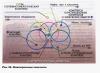
How does a carburetor work?
The following figure will help you understand its operating principle.
This is the simplest version of the carburetor, one can say that it only explains its structure and the main idea. Gasoline is in the float chamber at a constant level, which is maintained by the operation of the needle valve. Through the air filter, air is drawn into the engine cylinders. It passes through the mixing chamber, thanks to the narrowing there, in this place a vacuum is created in relation to the float chamber, in which the level of atmospheric pressure is maintained.
Due to the resulting pressure difference, fuel enters the mixing chamber. Passing through the nozzle, it breaks into small droplets, evaporates and mixes with air, resulting in the formation of a fuel assembly that enters the engine cylinders. The relationship between these components depends on the position of the carburetor damper, which is associated with the position of the accelerator pedal. The harder it is pressed on the car, the more the damper is open, the higher the degree of vacuum and the more gasoline is supplied to form the mixture.
Purpose of the economizer
At the moment when the damper is almost completely open, the car engine experiences maximum loads, which means it needs to overcome them. more gasoline than during normal operation. At the same time, the economizer begins to work, more fuel is supplied to form the mixture, and the mixture becomes enriched. Its purpose and design, as well as why an economizer is needed, becomes clear from the figure:

The carburetor throttle valve is connected to a special valve through rods and levers. When it is fully open, it triggers and additional quantity gasoline, passing through the economizer jet, goes to form fuel assemblies. This supply of fuel causes the mixture to become richer and ensures that the engine operates under increased load. When the gas pedal is released, the damper closes, the spring closes the valve and the economizer stops operating.
Structurally, the economizer device can be made in various ways, we will not touch on their specific implementation, because For the carburetor, after the advent of injection controllers, the development history ended.
Forced idle speed economizer (EFH)
When considering a car economizer, one cannot ignore such a device as the EPHH. It has a completely different purpose than a conventional economizer. If the latter, as we have just examined, enriches the fuel mixture under significant loads, then EPHH, on the contrary, ensures fuel economy. Forced idle mode – special option movements.
As a rule, this is associated with engine braking when driving downhill or coasting when the speed is turned on and the gas is released. EPHH complements the idle system available in the carburetor. It supplies fuel to the engine when the throttle is closed. In this case, due to the vacuum created underneath, the fuel passes through a special idle channel through the nozzle and enters the engine, which ensures its operation in this mode.
However, if the car is coasting or downhill, the crankshaft rotates at a higher frequency than is typical in idle mode, which causes increased gasoline consumption and reduces the efficiency of engine braking. To eliminate this, the EPHH is triggered and the flow of fuel stops. In forced idling mode, the flow of gasoline is interrupted by a solenoid valve controlled by a fairly simple electronic unit.

The initial data for the activation of the EPHV (solenoid valve) are the sensor signal about a closed damper and an increased number of crankshaft revolutions. This mode is currently supported by EPKH:
- the speed of movement will not decrease when the throttle is released;
- the gear will not be switched off and the car will begin to move in normal idle mode;
- the driver will not press the gas pedal and the movement will continue with increased speed, the economizer will turn off based on the damper position.
The operation of the economizer as part of the carburetor ensures enrichment of the fuel assembly at increased load, as well as fuel economy and better engine braking efficiency in forced idle mode.