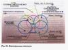
Image of circles in isometric projection
Let's look at how circles are depicted in an isometric projection. To do this, let's draw a cube with circles inscribed in its faces (Fig. 3.16). Circles located respectively in planes perpendicular to the axes x, y, z are depicted in isometry as three identical ellipses.
Rice. 3.16.
To simplify the work, ellipses are replaced by ovals outlined by circular arcs; they are constructed as follows (Fig. 3.17). Draw a rhombus into which an oval should fit, depicting this circle in an isometric projection. To do this, the axes are plotted from the point ABOUT in four directions segments equal to the radius of the depicted circle (Fig. 3.17, A). Through the received points a, b, c, d draw straight lines to form a rhombus. Its sides are equal to the diameter of the depicted circle.

Rice. 3.17.
From the vertices of obtuse angles (points A And IN) describe between points A And b, and also With And d arc radius R, equal to the length of the straight lines Va or Bb(Fig. 3.17, b).
Points WITH and D lying at the intersection of the diagonal of the rhombus with straight lines Va And Bb, are the centers of small arcs conjugating large ones.
Small arcs are described with a radius R, equal to the segment Sa (Db).
Construction of isometric projections of parts
Let's consider the construction of an isometric projection of a part, two views of which are given in Fig. 3.18, A.
The construction is carried out in the following order. First, draw out the original shape of the part - a square. Then ovals are built to represent an arc (Fig. 3.18, b) and circles (Fig. 3.18, c).

Rice. 3.18.
To do this, find a point on a vertical plane ABOUT, through which the isometric axes are drawn X And z. This construction produces a rhombus into which half of the oval is inscribed (Fig. 3.18, b). Ovals on parallel planes are constructed by moving the centers of the arcs to a segment equal to the distance between these planes. Double circles in Fig. Figure 3.18 shows the centers of these arcs.
On the same axes X And z build a rhombus with a side equal to the diameter of the circle d. An oval is inscribed in the rhombus (Fig. 3.18, c).
Find the center of the circle on a horizontally located face, draw isometric axes, build a rhombus into which an oval is inscribed (Fig. 3.18, G).
The concept of dimetric rectangular projection
The location of the dimetric projection axes and the method of their construction are shown in Fig. 3.19. Axis z carried vertically, axis X– at an angle of about 7° to the horizontal, and the axis at forms an angle of approximately 41° with the horizontal (Fig. 3.19, A). You can construct axes using a ruler and compass. To do this from the point ABOUT laid horizontally to the right and left in eight equal divisions (Fig. 3.19, b). Perpendiculars are drawn from the extreme points. Their height is equal to: for perpendicular to the axis X - one division, for perpendicular to the axis at- seven divisions. The extreme points of the perpendiculars are connected to point O.

Rice. 3.19.
When drawing a dimetric projection, as well as when constructing a frontal one, the axial dimensions at is reduced by 2 times, and along the axes X And z postponed without cuts.
In Fig. Figure 3.20 shows a dimetric projection of a cube with circles inscribed in its faces. As can be seen from this figure, circles in dimetric projection are depicted as ellipses.

Rice. 3.20.
Technical drawing
Technical drawing – This is a visual image made according to the rules of axonometric projections by hand, by eye. It is used in cases where you need to quickly and clearly show the shape of an object on paper. This is usually necessary when designing, inventing and rationalizing, as well as when learning to read drawings, when using a technical drawing you need to explain the shape of a part presented in the drawing.
When performing a technical drawing, they adhere to the rules for constructing axonometric projections: the axes are placed at the same angles, the dimensions along the axes are also reduced, the shape of the ellipses and the construction sequence are observed.
8.1. Frontal dimetric projections of circles. If they want some elements in the axonometric image. for example, circles (Fig. 64) are kept undistorted, then a frontal dimetric projection is used. The construction of a frontal dimetric projection of a part with a cylindrical hole, two views of which are given in Figure 64, a, is performed as follows:
- Using the x, y, z axes, draw thin lines to outline the external shape of the part (Fig. 64, b).
- Find the center of the hole on the front face. The axis of the hole is drawn through it parallel to the y-axis and half the thickness of the part is laid on it. The center of the hole located on the back face is obtained.
- From the obtained points, as from centers, circles are drawn, the diameter of which is equal to the diameter of the hole (Fig. 64, c).
- Remove excess lines and trace the visible outline of the part (Fig. 64, d).
Rice. 64. Construction of a frontal dimetric projection
In your workbook, construct a frontal dimetric projection of the part shown in Figure 64, a. Point the y-axis in the other direction. Enlarge the image size approximately twice.
8.2. Isometric projections of circles. The isometric projection of a circle (Fig. 65) is a curve called an ellipse. Ellipses are difficult to construct. In drawing practice, ovals are often built instead. An oval is a closed curve outlined by arcs of circles. It is convenient to construct an oval by fitting it into a rhombus, which is an isometric projection of a square.

Rice. 65. Image in isometric projection of circles inscribed in a cube
The construction of an oval inscribed in a rhombus is performed in the following sequence.
First, a rhombus is built with a side equal to the diameter of the depicted circle (Fig. 66, a). To do this, the isometric x and y axes are drawn through point O. On them, from point O, segments equal to the radius of the depicted circle are laid. Through points a, b, c and d, draw straight lines parallel to the axes; get a rhombus.

Rice. 66. Constructing an oval
The major axis of the oval is located on the major diagonal of the rhombus.
After this, an oval is inscribed in the rhombus. To do this, arcs are drawn from the vertices of obtuse angles (points A and B). Their radius R is equal to the distance from the vertex of an obtuse angle (points A and B) to points c, d or a, b, respectively (Fig. 66, b).
Straight lines are drawn through points B and a, B and b. At the intersection of straight lines Ba and Bb with the larger diagonal of the rhombus, points C and D are found (Fig. 66, a). These points will be the centers of the small arcs. Their radius R1 is equal to Ca (or Db). Arcs of this radius smoothly connect the large arcs of the oval.
We examined the construction of an oval lying in a plane perpendicular to the z axis (oval 1 in Figure 65). Ovals located in planes perpendicular to the y-axis (oval 2) and the x-axis (oval 3) are also constructed. Only for oval 2 the construction is carried out on the x and z axes (Fig. 67, a), and for oval 3 - on the y and z axes (Fig. 67, b). Let's consider how the studied constructs are applied in practice.

Rice. 67. Construction of ovals: a lying in a plane perpendicular to the y-axis; b - lying in a plane perpendicular to the x axis

Rice. 68. Construction of an isometric projection of a part with a cylindrical hole
8.3. A method for constructing axonometric projections of objects with round surfaces. Figure 68a shows an isometric projection of the plank. It is necessary to depict a cylindrical hole drilled perpendicular to the front edge. The construction is done like this:
- Find the center of the hole on the front face. Determine the direction of the isometric axes to construct a rhombus (see Fig. 65). Axes are drawn from the found center (Fig. 68, a) and segments equal to the radius of the circle are laid on them.
- They are building a rhombus. Draw it along a large diagonal (Fig. 68, b).
- Describe large arcs. Find the centers for small arcs (Fig. 68.c).
- Small arcs are drawn from the found centers.
The same oval is built on the back face, but only its visible part is outlined (Fig. 68, d).

In some cases, it is more convenient to begin constructing axonometric projections by constructing a base figure. Therefore, let us consider how flat geometric figures located horizontally are depicted in axonometry.
1. square shown in Fig. 1, a and b.
Along the axis X lay down the side of the square a, along the axis at- half a side a/2 for frontal dimetric projection and side A for isometric projection. The ends of the segments are connected by straight lines.
Rice. 1. Axonometric projections of a square:
2. Construction of an axonometric projection triangle shown in Fig. 2, a and b.
Symmetrical to a point ABOUT(origin of coordinate axes) along the axis X lay aside half the side of the triangle A/ 2, and along the axis at- its height h(for frontal dimetric projection half height h/2). The resulting points are connected by straight segments.

Rice. 2. Axonometric projections of a triangle:
a - frontal dimetric; b - isometric
3. Construction of an axonometric projection regular hexagon shown in Fig. 3.
Axis X to the right and left of the point ABOUT lay down segments equal to the side of the hexagon. Axis at symmetrical to the point ABOUT lay down the segments s/2, equal to half the distance between opposite sides of the hexagon (for frontal dimetric projection, these segments are halved). From points m And n, obtained on the axis at, swipe right and left parallel to the axis X segments equal to half the side of the hexagon. The resulting points are connected by straight segments.

Rice. 3. Axonometric projections of a regular hexagon:
a - frontal dimetric; b - isometric
4. Construction of an axonometric projection circle .
Frontal dimetric projection convenient for depicting objects with curvilinear outlines, similar to those shown in Fig. 4.

Fig.4. Frontal dimetric projections of parts
In Fig. 5. given frontal dimetric projection of a cube with circles inscribed in its faces. Circles located on planes perpendicular to the x and z axes are represented by ellipses. The front face of the cube, perpendicular to the y-axis, is projected without distortion, and the circle located on it is depicted without distortion, i.e., described by a compass.

Fig.5. Frontal dimetric projections of circles inscribed in the faces of a cube
Construction of a frontal dimetric projection of a flat part with a cylindrical hole .
The frontal dimetric projection of a flat part with a cylindrical hole is performed as follows.
1. Construct the outline of the front face of the part using a compass (Fig. 6, a).
2. Straight lines are drawn through the centers of the circle and arcs parallel to the y-axis, on which half the thickness of the part is laid. The centers of the circle and arcs located on the rear surface of the part are obtained (Fig. 6, b). From these centers a circle and arcs are drawn, the radii of which must be equal to the radii of the circle and arcs of the front face.
3. Draw tangents to the arcs. Remove excess lines and outline the visible contour (Fig. 6, c).

Rice. 6. Construction of a frontal dimetric projection of a part with cylindrical elements
Isometric projections of circles .
A square in isometric projection is projected into a rhombus. Circles inscribed in squares, for example, located on the faces of a cube (Fig. 7), are depicted as ellipses in an isometric projection. In practice, ellipses are replaced by ovals, which are drawn with four arcs of circles.

Rice. 7. Isometric projections of circles inscribed in the faces of a cube
Construction of an oval inscribed in a rhombus.
1. Construct a rhombus with a side equal to the diameter of the depicted circle (Fig. 8, a). To do this, through the point ABOUT draw isometric axes X And y, and on them from the point ABOUT lay down segments equal to the radius of the depicted circle. Through dots a, b, WithAnd d draw straight lines parallel to the axes; get a rhombus. The major axis of the oval is located on the major diagonal of the rhombus.
2. Fit an oval into a rhombus. To do this, from the vertices of obtuse angles (points A And IN) describe arcs with radius R, equal to the distance from the vertex of the obtuse angle (points A And IN) to points a, b or s, d respectively. From point IN to the points A And b draw straight lines (Fig. 8, b); the intersection of these lines with the larger diagonal of the rhombus gives the points WITH And D, which will be the centers of small arcs; radius R 1 minor arcs is equal to Sa (Db). Arcs of this radius conjugate the large arcs of the oval.

Rice. 8. Construction of an oval in a plane perpendicular to the axis z.
This is how an oval is built, lying in a plane perpendicular to the axis z(oval 1 in Fig. 7). Ovals located in planes perpendicular to the axes X(oval 3) and at(oval 2), build in the same way as oval 1, only oval 3 is built on the axes at And z(Fig. 9, a), and oval 2 (see Fig. 7) - on the axes X And z(Fig. 9, b).

Rice. 9. Construction of an oval in planes perpendicular to the axes X And at
Constructing an isometric projection of a part with a cylindrical hole.
If on an isometric projection of a part you need to depict a through cylindrical hole drilled perpendicular to the front face, shown in the figure. 10, a.
The construction is carried out as follows.
1. Find the position of the center of the hole on the front face of the part. Isometric axes are drawn through the found center. (To determine their direction, it is convenient to use the image of the cube in Fig. 7.) On the axes from the center, segments equal to the radius of the depicted circle are laid (Fig. 10, a).
2. Construct a rhombus, the side of which is equal to the diameter of the depicted circle; draw a large diagonal of the rhombus (Fig. 10, b).
3. Describe large oval arcs; find centers for small arcs (Fig. 10, c).
4. Small arcs are carried out (Fig. 10, d).
5. Construct the same oval on the back face of the part and draw tangents to both ovals (Fig. 10, e).

Rice. 10. Construction of an isometric projection of a part with a cylindrical hole
In the article the essence of the method was described parallel design and its properties. But as practice shows, it is difficult for students to perceive theoretical concepts without demonstration with specific examples.
In this article we will show how to use the properties of parallel projection and the properties of plane figures known to schoolchildren (triangle, parallelogram, trapezoid, circle and hexagon) for images of these figures during parallel design .
1. Triangle image
1) Any triangle (rectangular, isosceles, regular) is depicted as an arbitrary triangle in a convenient location in the figure.

2) If ΔA 1 B 1 C 1 is rectangular, then the image of the directions of its two heights (legs) is given. The altitude lowered to the hypotenuse and the center of the inscribed circle are arbitrarily depicted. The image of a perpendicular lowered from a given point of the hypotenuse to any leg is a segment parallel to the other leg.

3) If ΔA 1 B 1 C 1 is isosceles, then the image of the median B 1 D 1 is the image of the height and bisector ΔA 1 B 1 C 1 . The images of the center of the inscribed and circumscribed circles belong to BD.

4) If ΔA 1 B 1 C 1 is regular (equilateral), then the centers of the inscribed and circumscribed circles coincide and lie at the point of intersection of the medians. Therefore, the construction of an image of this triangle cannot be arbitrary if, for example, the center of one of these circles is given.

2. Image of a parallelogram
Any given parallelogram A 1 B 1 C 1 D 1 (including a rectangle, square, rhombus) can be represented by an arbitrary parallelogram ABCD.
On the image of an arbitrary parallelogram, images of its two heights drawn from one vertex can be constructed arbitrarily. Moreover, the heights drawn from the vertex of the acute angle of the parallelogram - the original - lie outside the parallelogram, and the heights drawn from the vertex of the obtuse angle lie inside it.
1) If A 1 B 1 C 1 D 1 is a rhombus, then a pair of mutually perpendicular straight lines is determined in the image - these are the diagonals ABCD. Therefore, it is arbitrarily possible to construct an image of only one height from a given vertex of a rhombus to its side.
When depicting another height of a rhombus, take into account that the bases of these heights lie on a straight line parallel to the diagonal of the rhombus.
Perpendiculars dropped to the sides of a rhombus from any point on its diagonal are depicted in a similar way.

2) If A 1 B 1 C 1 D 1 is a square, then its image is an arbitrary parallelogram ABCD. Moreover, images of heights, bisectors, angles, perpendiculars to sides cannot be constructed arbitrarily.
3. Image of a trapezoid
Any trapezoid A 1 B 1 C 1 D 1 (as well as isosceles and rectangular) can be represented by an arbitrary trapezoid ABCD.
1) If A 1 B 1 C 1 D 1 is a general trapezoid, then the image of its height and one of the perpendiculars lowered from the base point to the sides can be constructed arbitrarily.

2) If A 1 B 1 C 1 D 1 is a rectangular trapezoid, then C 1 B 1 ⊥ A 1 B 1 , the image of the height of the trapezoid is already given in the figure, so only the perpendicular to the inclined side can be arbitrarily depicted.

3) If A 1 B 1 C 1 D 1 is an isosceles trapezoid (there is an axis of symmetry), then the image of the height is a segment connecting the midpoints of the upper and lower bases of the trapezoid (or parallel to it).

4. Circle image
The parallel projection of a circle is an ellipse. The center of the circle in the image is the intersection point of the conjugate diameters of the ellipse. Two diameters of a circle (ellipse) are called conjugate if each of them bisects all chords parallel to the other diameter.

4. Image of a regular hexagon
A regular hexagon A 1 B 1 C 1 D 1 E 1 F 1 is depicted as follows: first, an arbitrary parallelogram BCEF is drawn and its diagonals BE and CF are drawn; then, from the point of their intersection O, equal segments of arbitrary length (but larger than half of the side BC) are laid parallel to the sides BC and EF. The ends of the constructed segments are vertices A and D.

So, we looked at all sorts of options. images of flat figures on a plane using the parallel projection method .
In the next article we will look at image of spatial figures on a plane.