- Page 3 You have acquired a product made by ZEISS. Please read this operating manual before using your instrument for the first time to make sure that its quality is maintained and you can utilize your instrument reliably for a long time. Page 4 Violations will entail an obligation to pay compensation. All rights reserved in the event of granting of patents or registration of a utility model. Issued by: Carl Zeiss Microscopy GmbH Carl-Zeiss-Promenade 10 D-07745 Jena, Germany [email protected] www.zeiss.com/microscopy...
Page 5: Table Of Contents
DESCRIPTION ......................13 Indication for use ......................13 Microscope system ..................... 13 Microscope sets and fields of application .................. 14 Interfaces on the microscope body Stemi 305 ............... 15 System overview ....................... 16 Technical data... ...................18 INSTALLATION ......................21 General information .... ................. 21 Installing the stereo microscope .................. Page 6 CONTENTS Stereo microscope ZEISS Stemi 305 APPENDIX .................40 List of abbreviations .............. ....... 40 Troubleshooting ......... 41 List of illustrations ............. .........42 Index ...........................43 435063-7044-001 01/2015... Page 7: Introduction
ZEISS INTRODUCTION General information The stereo microscope Stemi 305 has been designed, produced and tested in compliance with the standards DIN EN 61010-1 (IEC 61010-1) and IEC 61010-2-101 "Safety Requirements for Electrical Measuring, Control and Laboratory Equipment ". The device meets the requirements of the EC Directive 98/79/EC Annex 1 regarding ivd products and the EC RoHS Directive 2011/65/EC and carries the mark.- Page 9 Samples must also be disposed of appropriately in accordance with the applicable statutory provisions and internal work instructions. The stereo microscope Stemi 305 incl. its original accessories may only be used for the applications described in this operating manual. The manufacturer cannot assume any liability for other applications, including those of individual modules or single components. Page 10 If it is intended to operate the Stemi 305 with an external fiber optical cold light source, please refer to the appropriate operating instructions incl. the safety provisions contained in them before commissioning the light source.
- Page 11 Stereo microscope INTRODUCTION Stemi 305 Warranty notes ZEISS Fig. 1 Warning and information labels on the device LED aperture, transmitted-light illuminators LED aperture, spot illuminator K LED LED aperture, ring illuminator K LED, segmentable LED aperture, double spot illuminator K LED LED aperture, integrated vertical illuminator Fig.
Page 13: Description
They are used, moreover, in biological and medical laboratories, in industrial manufacture and quality assurance. Stemi 305 is envisaged for applications in biology and in medicine for the analysis of blood and/or tissue samples from the human body. Applications in the field of diagnostic medicine are explicitly excluded, except for the field of medical research.Page 15: Interfaces On The Microscope Body Stemi 305
Interfaces on the Stemi 305 with stand K LED (schematic diagram) Thanks to the interface ∅ 76 mm, the Stemi 305 can also be used in conjunction with other stands of the modular kit of the Stereo system – and other ZEISS stereo microscopes such as e.g.- Page 17 Stereo microscope DESCRIPTION Stemi 305 System overview ZEISS 01/2015 435063-7044-001...
- Page 19 Stereo microscope DESCRIPTION Stemi 305 Technical data ZEISS Ambient conditions Storage (in packaging) Admissible ambient temperature ..............+10 to +40 °C Admissible relative humidity .. .........max. 75% at +35 °C (non-condensing) Transport (in packaging) Admissible ambient temperature ......-40 to +70 °C Operation Admissible ambient temperature . ............. Page 20 Stereo microscope ZEISS Technical data Stemi 305 Optical risk group classification acc. to DIN EN 62471:2009 Overall device ............... LED risk group 2 acc. to DIN EN 62471:2009 Integrated vertical illumination ..........LED risk group 2 acc. to DIN EN 62471:2009 Spot illuminator K LED (reflected illumination) .......
Page 21: Installation
Before installing and commissioning the device, make sure to read the Notes on Instrument Safety carefully (see Section 1.2, Page 8). The Stemi 305 with the necessary tools and optional equipment is delivered in several standard packages. Take all units out of the packaging and check them for completeness according to the delivery note. Page 22 INSTALLATION Stereo microscope ZEISS Installing the stereo microscope Stemi 305 Insert the connection cable (Fig. 10/3) supplied with the device into the socket on the Stemi body and in the socket on the Stemi mount. Insert glass plate or B/W plastic plate (Fig. 10/7) in the mount in the base of the stand. Page 23: Mounting Optional Components
Stereo microscope INSTALLATION Stemi 305 Mounting optional components ZEISS Mounting optional components 3.3.1 Mounting additional reflected-light illuminator Various reflected-light illuminators can be used, depending on the case of application. For fastening, defined interfaces have been provided on the microscope. 3.3.1.1... Page 24 INSTALLATION Stereo microscope ZEISS Mounting optional components Stemi 305 3.3.1.2 Mounting ring illuminator K LED (segmentable) Mounting ring illuminator to microscope body Insert the connection cable (Fig. 13/1) of the ring illuminator (Fig. 13/4) into the lower socket (Fig. 13/2) of the Stemi mount and into the socket of the ring illuminator. - Page 25 Stereo microscope INSTALLATION Stemi 305 Mounting optional components ZEISS 3.3.1.3 External fiber-optic illumination Switch on external fiber-optic illumination (Fig. 15/1), adjust illumination intensity and set illumination by bending the two goose necks (Fig. 15 /2) so that the specimen is optimally lit.
Page 27: Operation
Stereo microscope OPERATION Stemi 305 Adjusting the stereo microscope ZEISS OPERATION Adjusting the stereo microscope The stereo microscope has been connected and switched ON. Place specimen (Fig. 18/7) centrally on the glass or plastic plate (Fig. 18/6) and illuminate it (Fig. 18/5).Page 29: Spot Illuminator
Stereo microscope OPERATION Stemi 305 Setting reflected-light illumination ZEISS 4.2.2 Spot illuminator Push spot illuminator in the guide to the required height (Fig. 21/2). In the lower positions, an oblique light effect is created to produce cast shadows for enhancing surface structures.Page 31: Controller K LED
ZEISS 4.2.5 Controller K LED The controller K (Fig. 24/4) is used to activate the vertical illumination of the Stemi 305 body or the ring illuminator in case of applications with boom stands A or U or additional stands. ...Page 33: Transmitted-light Unit In Stand K Lab
Stereo microscope OPERATION Stemi 305 Transmitted-light illuminators ZEISS 4.3.2 Transmitted-light unit in stand K LAB Switch transmitted-light illumination ON by pressing the lower knob (Fig. 26/1). With the transmitted light ON, turn this knob to adjust the illumination intensity.Page 35: Maintenance
Stereo microscope CARE, MAINTENANCE AND SERVICE Stemi 305 Maintenance ZEISS Maintenance 5.2.1 Replacing the power unit Only the desktop power unit specified by the manufacturer may be used. Make sure that the mains plug is removed from the socket before the instrument is opened.Page 37: Opening The Stand Cover Plate, Stand K Lab
Stereo microscope CARE, MAINTENANCE AND SERVICE Stemi 305 Maintenance ZEISS 5.2.3 Opening the stand cover plate, stand K LAB The transmitted-light base (Fig. 29/1) can be removed from the stand cover plate (Fig. 29/3) for cleaning or for removal of any foreign matter which might have fallen inadvertently.Page 39: Product Disposal
The product contains electronic components which must be disposed of according to the requirements of the 2002/19/EC WEEE Directive and not as domestic waste. In addition, the national regulations must be complied with. For details on disposal and recycling please refer to your relevant ZEISS sales or service organization. 01/2015 435063-7044-001...Page 41: Troubleshooting
Stereo microscope APPENDIX Stemi 305 Troubleshooting ZEISS Troubleshooting Description of fault Cause of error Troubleshooting Stereo microscope illumination Power supply interrupted. Check or establish connection to cannot be switched ON. power supply. Switch power switch Power switch not switched ON on back of stereo microscope ON.Page 43: Index
Stereo microscope APPENDIX Stemi 305 Index ZEISS Index Adjusting the stereo microscope ....27 Maintenance ..........35 Ambient Conditions ........19 Microscope system ........ 13 Ambient temperature .......19 Mixed light ............ 28 Apertures for LED radiation ......11 Operation ........... .. 27 Bright field ............
Page 8: Notes On Instrument Safety
If it becomes apparent that the safety measures are no longer effective, the device must be taken out of service and secured against being used again unintentionally. Please contact a ZEISS service agency or the Carl Zeiss Microscopy Service to have the instrument repaired. The Stemi 305 Information regarding instrument safety and installation conditions 435063- 6044-008 and the Stemi 305 short operating instructions 435063-8044-000 as well as the operating instructions regarding the light sources also must be observed.Page 12: Warranty Notes
No maintenance or repair work may be performed on the microscopes which exceed the activities specified in this operating manual. Repair may only be performed by ZEISS Service or by persons specifically authorized by it. Should any malfunctions occur on the device, please first contact the Carl Zeiss Microscopy Service or, abroad, the ZEISS representative in your area.Page 14: Microscope Sets And Fields Of Application
Fig. 5 Stemi 305 LAB microscope set Stemi 305 MAT: − Stemi 305 ESD body in stand K MAT − integrated controllable vertical illuminator − segmentable ring illuminator for reflected light − for industrial quality assurance and manufacture − ESD-capable thanks to its antistatic surface Fig.Page 16: System Overview
DESCRIPTION Stereo microscope ZEISS System overview Stemi 305 System overview 435063-7044-001 01/2015...Page 18: Technical Data
ZEISS Technical data Stemi 305 Technical data Microscope system Stemi 305 EDU Weight Dimensions ......... Stemi 305 in stand K EDU 4.6 kg Microscope system Stemi 305 LAB Weight Dimensions ......... Stemi 305 in stand K LAB 6.2 kg 435063-7044-001...Page 26: Connecting Stereo Microscope To The Power Supply
The slight image offset which is due to the additional glass distance is taken into account on the diopter scale by the zero position not being indicated by the white dot (Fig. 16/W), but by a red dot (Fig. 16/R ). Eyepieces with pre-inserted eyepiece plates are available directly from ZEISS. Connecting stereo microscope to the power supply...Page 28: Setting Reflected-light Illumination
Setting reflected-light illumination Stemi 305 Setting reflected-light illumination 4.2.1 Integrated vertical illuminator Each Stemi 305 body features a vertical illuminator of its own. If no second reflected-light illumination has been installed, the vertical illuminator is operated as described below: ...Page 30: Ring Illuminator
OPERATION Stereo microscope ZEISS Setting reflected-light illumination Stemi 305 4.2.4 Ring illuminator pressing front button (Fig. 23/2) successively, the user can change over between four illumination states of the ring illuminator (Fig. 23/3): 1 .Press: full circle 2. Press: semi-circle 3.Page 32: Transmitted-light Illuminators
OPERATION Stereo microscope ZEISS Transmitted-light illuminators Stemi 305 Transmitted-light illuminators 4.3.1 Transmitted-light module in stand K EDU Switch transmitted-light illumination ON by pressing the lower knob (Fig. 25/2). With the transmitted light ON, turn this knob to adjust the illumination intensity.Page 34: Care, Maintenance And Service
CARE, MAINTENANCE AND SERVICE Stereo microscope ZEISS Care Stemi 305 CARE, MAINTENANCE AND SERVICE Care Care of the devices is restricted to the following operations: The devices are not equipped with special equipment protecting them from corrosive, potentially infectious, toxic and radioactive or other samples that may be hazardous to health. If you handle such samples, be sure to observe all legal requirements, in particular the relevant national accident prevention regulations.Page 36: Opening The Stand Cover Plate, Stand K Edu
CARE, MAINTENANCE AND SERVICE Stereo microscope ZEISS Maintenance Stemi 305 5.2.2 Opening the stand cover plate, stand K EDU The stand cover plate (Fig. 28/1) may be removed for cleaning or to remove any foreign matter which might fallen in inadvertently .Page 38: Wearing Parts
To ensure your stereo microscope is optimally set and also operates correctly over an extended period of time, we recommend that you conclude a service/maintenance contract with ZEISS. For reordering or in case of service, contact your nearest regional ZEISS representative. 435063-7044-001...Page 40: Appendix
APPENDIX Stereo microscope ZEISS List of abbreviations Stemi 305 APPENDIX List of abbreviations Bright field Cold Light Deutsche Industrie-Norm (German Industrial Standard) Dark field Europäische Norm (European Standard) International Electrotechnical Commission Internal Protection (Type of enclosure) In-vitro diagnostics Light Emitting Diode Relief contrast (oblique light) Schwarz/weiß...Page 42: List Of Illustrations
Stemi 305 LAB microscope set .................... 14 Fig. 6 Stemi 305 MAT microscope set ..................14 Fig. 7 Interfaces on the Stemi 305 with stand K LED (schematic diagram) ........15 Fig. 8 Front optics, Stemi 305 (example) ..................15 Fig. 9 Removing caps...........................Activision AVC-305 COLOR video intercom calling panelfor 1 subscriber color . Select this calling panel only for video intercoms that support panels withPAL color format . AVC-305 COLOR is made in a vandal-proof metal case of an overhead type, which allows it to be installed in places with a high risk of vandalism and theft.
The calling panel is used as an external video surveillance intercom. Using AVC-305 COLOR, you can maintain voice communication with the visitor and at the same time carry out video surveillance of the space in front of the calling panel. Thanks to the presence of hidden infrared illumination, the image will be visible even in the complete absence of lighting.
ATTENTION! Activision AVC-305 COLOR calling panels are available in several body colors: silver ANTIQUE, COPPER, BLACK. When ordering, indicate the desired color in the comments.
You can connect and to the color intercom. Black and white panels are less expensive and show better in the dark.
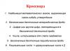
Characteristics of the AVC-305 COLOR calling panel
- Matrix: CCD SONY 1.3" color
- Color format: PAL
- Resolution: 350TVL
- Lens: f=3.7mm, F=3.5 Pinhole. Wide angle.
- Sensitivity: 0.5 Lux
- Number of connected subscribers: 1
- Availability of infrared illumination: yes up to 0.5m (hidden)
- Power: from video intercom 12V
- Viewing angle: 75 horizontally and 55 vertically
- Operating temperature range: -30…+55
- Protection code: IP43
- Relative humidity: up to 98%
- Dimensions 122x40x24
Equipment for the AVC-305 COLOR calling panel:
- Video intercom calling panel - 1 pc.
- Dowel - 2 pcs.
- Screw - 2 pcs.
- Decorative plug - 2 pcs.
- Instruction manual - 1 piece.
- Canopy for protection from precipitation - 1 pc.
- Rotating bracket 30 degrees - 1 pc.
Installation and connection of AVC-305 COLOR
In order to install the calling panel, it is necessary to perform the following operations:
- decide on the installation location (fixed door leaf or wall)
- drill holes for mounting
- lay a communication line for connection (avoid laying near power cables)
- connect the calling panel to the communication cable according to the instructions
- test the correct operation of the video intercom and calling panel
- screw the calling panel in a pre-prepared place
- plug the holes on the calling panel with decorative plugs.
Attention! It is not recommended to install the calling panel on the moving part of the door to avoid damage to the built-in video camera.
There are 6 wires on the back of the calling panel, 2 of which are intended to transmit a signal to open the lock, and the rest are for connecting the AVC-305 COLOR calling panel to the video intercom. Most calling panels use a 4-wire connection scheme. For convenience and ease of installation, all wires are highlighted in different colors; the Activision AVC-305 COLOR calling panel should be connected according to the diagram:
Black (general)
Red (+12V)
Yellow (audio)
White (video)
As can be seen from the connection diagram, the panel is powered from the video intercom. The maximum length of the line from the video intercom to the calling panel declared by the manufacturer is 50 meters. In practice, it was possible to achieve a line length of up to 100m, but only when using an RG-6 cable in combination with a 2x1.5 cable. For short distances up to 15 meters, we recommend using UTP 5-e twisted pair cable due to its low cost.
Video review of AVC-305 COLOR
This article will discuss connecting a video intercom for a private home using the AXIOS video intercom system as an example. This system consists of the AXI-305 NEW calling panel and the AXI-LA 04 subscriber device (video monitor), to which an automatic lock from any manufacturer is connected.
Layout of video intercom devices
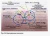
A typical layout of video intercom devices is shown in Figure 1.
Rice. 1. Typical layout of video intercom devices with one calling panel
As can be seen from Figure 1, some of the system’s devices are installed inside the house (subscriber device and power supply), and some of the devices are installed on the gate (calling panel, lock control unit and automatic lock). Devices inside and outside the house are connected by a communication line through which power is supplied and video and audio signals are transmitted, as well as calling and control signals.
What you need to install a video intercom
Tools and materials
To perform installation of a video intercom, the following minimum set of tools is required:
- A hammer drill with a set of drills and blades for chipping walls;
- Drill or screwdriver;
- Angle grinder;
- Screwdriver set;
- Pliers;
- Hammer;
- A container for mixing putty and a spatula.
The list and quantity of materials used depends on the method of laying cables, the distance and placement of actuators and other equipment. The following materials are most often needed:
- Two-core wire for power supply. It is necessary to connect a power cable with a cross-section of 2x2mm to the lock or use a BUZ;
- ShSM (wire for video intercoms and alarm systems) or KVK-P-3 (combined cable for video surveillance) or, as a last resort, shielded twisted pair (UTP wire);
- Sockets and plugs;
- Corrugated electrical pipes;
- Plaster, alabaster or putty.
Link
Communication line requirements
- Twisted pair UTP Cat 5 4x0.2 mm2 - up to 28 m;
- Twisted pair UTP Cat 5 (AWG 22) 4x0.3 mm2 - up to 50 m;
- Wire 4x0.5 mm2 - up to 80 m.

Rice. 2. Maximum communication line length depending on cable type
However, practical experience in installing intercom systems has shown that twisted pair cables provide acceptable communication quality only if its length does not exceed 10 meters! Otherwise, the video image suffers primarily due to interference and interference. In most cases, it is better to use specialized shielded cables for video surveillance or alarms in the communication line. For example, ShSM or KVK-P-3.
Installation and connection of the calling panel
The calling panel should be mounted primarily on fixed building structures: the wall of a house or a permanent gate post. It is strongly recommended not to install the device on moving devices - gates, gates or doors, as constant shaking can dislodge the lens inside the housing. Given the miniature size of the lens, even a small shift can become critical.
To prevent the lens from being illuminated by sunlight, it is necessary to use a sun visor or a corner-mounted bracket that is installed under the calling device and changes its viewing angle.

Rice. 3. Call panel with sun visor or corner bracket
Otherwise, sunlight may backlight visitors and only the silhouette will be visible on the screen, not the face.

Installation of the video intercom panel is carried out in the following order:
- The back cover is removed from the calling panel; . Drilling locations are marked through the mounting holes;
- All marked places are drilled and an additional through hole is drilled to lead the communication line wires and lock control into the yard;
- The communication line is connected to the contact strip of the calling panel in accordance with Fig. 7 and is brought into the house to the subscriber device;
- The wire running into the yard to control the lock is connected to the contacts of the electromechanical lock.
- Devices should only be connected to the network after all electrical connections have been completed.!
After checking all connections, the calling panel is attached to the base with special “secret” screws, which cannot be removed with a simple screwdriver.
Installation and connection of the lock
To open the lock, a voltage of 12V is required, which comes from the calling panel. There are two schemes for installing a power supply unit (PSU) in an intercom system:
- The power supply is installed in the house, the supply voltage comes through the communication line;
- The power supply for the subscriber device is installed in the house, and to power the calling panel and the lock, a second power supply is installed in close proximity to them.
The advantage of the first scheme is that only one power supply is used in the system. However, in a communication line the cross-section of the wires is small and, as the length of such a line increases, the DC voltage drops. In the case of an electromechanical lock, this voltage may not be enough to trigger its electromagnetic coil. Thus, in addition to the communication line, a powerful power cable with a minimum cross-section of 2mm2 must be installed to the lock. Especially if the lock is located more than 20 meters from the intercom. Or use a lock control unit (LCU) - this is a small-sized device that accumulates a 12V voltage from the communication line and gives a short current pulse (up to 3A) sufficient to open an electromechanical lock. The miniature dimensions of the BUZ allow it to be placed both in the calling panel body and in the lock body.
Installation and connection of the subscriber device
To avoid interference and interference, the subscriber device should be installed no closer than 30 cm from electrical lines.

Rice. 5. Installation height of the subscriber device

Rice. 6. Installation of the subscriber device on the wall
The device is mounted on a frame, which is attached to the wall using self-tapping screws and plastic dowels.
Please note the following:
- Disconnect the monitor from power supply before installation.
- Avoid sharp impacts and falling equipment!
- Connect devices to the network only after all electrical connections have been completed!
Switching of all video intercom devices
When using one calling panel, you must connect it to the “Panel 1” monitor connector. Observe the matching colors and purpose of the connecting wires of the monitor and panel (Fig. 7). If you use an additional calling panel, it should be connected to the “Panel 2” connector.

Rice. 7. Connection diagram of calling panels to the subscriber device
The “Panel 1” and “Panel 2” connectors have the same functionality (Fig. 7).
Purpose and colors of wires:
- Red: +12V
- White: Audio signal
- Black: Ground (GND)
- Yellow: Video signal
The electric lock is controlled using the normally open relay contacts (N.O.) of the calling panel.
The subscriber device is powered from an alternating current network with a voltage of 100...240V. The device is equipped with its own voltage converter.
ATTENTION! When connecting, observe the purpose of the connecting wires between the monitor and the panel.
After switching of all connections is completed, the operation of the intercom system is tested, and only after this the final installation of all units of the system is carried out.