fields. Determine the rate of change of the field induction modulus if the charge on the capacitor is q = 2.0 µC.
please write down
changes in the magnetic field if the charge on the capacitor is 1 nC.
1. The figure shows the direction of the magnetic field lines. In this magnetic field, a closed coil of wire is moved firstvertically upward so that the plane of the coil is parallel to the magnetic field induction lines (in the figure - situation A), then in the horizontal direction so that the plane of the coil is perpendicular to the magnetic field induction lines (in the figure - situation B). At what frame movement does the magnetic flux change?
1) Only in A 3) Both in A and B
2) Only in B 4) Neither in A nor in B
2. The closed loop is located at a certain angle to the magnetic induction lines. How will the magnetic flux change if the magnitude of the magnetic induction vector increases by 3 times?1) Will increase 3 times 3) Increase 6 times
2) Will decrease by 3 times 4) Will decrease by 9 times
3. The closed loop is located at a certain angle to the magnetic induction lines. How will the magnetic flux change if the area of the circuit decreases by 2 times, and the magnitude of the magnetic induction vector increases 4 times?1) Will increase by 2 times 3) Will increase by 4 times
2) Will decrease by 2 times 4) Will decrease by 4 times
4. The magnetic induction lines lie in the plane of the closed loop. How will the magnetic flux change if the magnitude of the magnetic induction vector increases by 3 times?1) Will increase 3 times 3) Increase 9 times
2) Will decrease by 3 times 4) Will not change
A circular coil of wire with an area of 20 cm2 is in a uniform magnetic field, the induction of which uniformly changes by 0.1 T in 0.4 s.The plane of the coil is perpendicular to the induction lines. What is the EMF generated in the coil?
Help, I missed it and can’t solve it! Just don’t unsubscribe, but explain the solution and I really need a drawing! In a homogeneousIn a magnetic field with an induction of 0.1 T, perpendicular to the induction lines there is a conductor 70 cm long, through which a current of 70 mA flows. Determine the force acting on the conductor. Make an explanatory drawing.
In a uniform magnetic field with a magnetic induction of 0.1 T, an electron moves in a vacuum at a speed of 3,106 m/s. What is the force acting on the electron if the angle between the direction of the electron's velocity and the induction lines is 90°? Make an explanatory drawing.
An electron flies into a uniform magnetic field perpendicular to the induction lines at a speed of 107 m/s. Determine the field induction if the electron described a circle with a radius of 1 cm. Make an explanatory drawing.
A coil with an area of 100 〖cm〗^2 is in a magnetic field with an induction of 5 Tesla. The plane of the coil is perpendicular to the field lines. Determine the average value of the induced emf when the field is turned off in 0.01 s.
1. As already indicated in § 2 of this chapter, when using the rotation method, the projection directions of the original remain unchanged, but the position of the original in space changes, which is achieved by rotating it around a certain axis. As the axis of rotation, a straight line is usually chosen, perpendicular to both oh something level planes nya, or a straight line of a level, since the constructions performed on a complex drawing when rotating around these straight lines are much simpler than the constructions when rotating around a straight line in general position. If it is necessary to rotate the original around an axis that is a straight line in general position, then by constructing additional types this rotation is reduced to a rotation around a straight line, perpendicular dicular level plane relative to one of the new projection planes. After performing the rotation on additional views, the results are returned to the front and top views.
When performing rotation around any axis υ It should be remembered that the rotating point A describes a circle located in a plane B, perpendicular to the axis of rotation υ (Fig. 185). Center WITH of this circle is the base of the perpendicular drawn from the rotated point A on the axis of rotation υ , or, in other words, the point of intersection with the axis of rotation υ plane B, in which the point rotates. It is quite obvious that all points of the original, when rotated around its axis, rotate through the same angle ω . The exception is those points of the original that are located on the axis of rotation; these points remain motionless when rotated.
2. Rotate a point around straight line perpendicular to the level plane. Let some point be given A, which rotates around a vertical line i. Plane G, at which point A describes a circle, being perpendicular to a vertical line i, will be the horizontal plane of the level (Fig. 186a). Circle with center at a pointWITH , which when rotated describes dot A, is depicted in the top view without distortion, and in the front view - as a straight segment perpendicular to the communication lines. To simplify the visual representation in Fig. 186a plane 2 aligned with the horizontal plane G, and in Fig. 187a plane 1 aligned with the frontal plane F.

For example, let's rotate a point A around a straight line i at a certain angle ω in the direction opposite to the clockwise movement (when viewed from above, Fig. 186b). To do this we carry out top view circle centered at a pointWITH= iand radius |AC |. Then we set the corner ASA= ω , teachin the indicated directione rotation. We getnew position Ā points A in the top view. Front view shows new position Ā points A will be defined in degenerate form G–G plane G, at which the point rotates A.
If the point A rotates around a straight line perpendicular to the frontal plane, then it will describe a circle in the frontal plane of the level F(Fig. 187a). This circle will be displayed without distortion in the front view, but in view e from above she image appears as a straight line segment perpendicular to the communication lines.
In Fig. 187b the point has been rotated A around a straight line i, perpendicular to the frontal plane at an angle ω in the direction of clockwise movement.


Thus, when rotating a point around a straight line, perpendicular to the frontal (horizontal) plane And, the point in the front (top) view moves ok appearance, but in appearance above (front)–By straight mine, perpendicular whether niyam communications.
3. Rotate a straight line . Since a straight line is defined by two of its points, the rotation of a straight line is reduced to the rotation of the points that define the straight line.
Let, for example, you want to rotate a line in general position around a vertical line i by an angle ω in the direction opposite to the clockwise movement (Fig. 188).
Selecting on a straight line l two arbitrary points 1
And 2
, let's rotate them around the axis i at the same angle ω in a given direction of rotation (in the top view, chord 1–  must be equal to the chord between the points marked with crosses). New provisions
  And
And
 points 1
And 2
will determine a new position
points 1
And 2
will determine a new position  given line l after its rotation through an angle ω in a given direction. Looking at triangles from above 1
–2
–i And
given line l after its rotation through an angle ω in a given direction. Looking at triangles from above 1
–2
–i And  –
– –i, we notice that the sides 1
–i And 2
–i of the first triangle are respectively equal to the sides
–i, we notice that the sides 1
–i And 2
–i of the first triangle are respectively equal to the sides  –i And
 –i of the second triangle, the angles between these sides are also equal. Therefore Δ 1
–2
–i
–i of the second triangle, the angles between these sides are also equal. Therefore Δ 1
–2
–i
 Δ
Δ  –
– –i and, therefore, | 1
–2|
=
|
–i and, therefore, | 1
–2|
=
| –
– |.
|.

Thus, when two points are rotated by the same angle around a vertical straight distance between them in the top view remains unchanged.
It's obvious that when rotating around a straight line perpendicular to the frontal plane, remains unchanged distance between points in front view.
These properties make it somewhat easier to construct a new position for a straight line after it has been rotated. Rotate a straight line l around a vertical line i by an angle ω in the direction opposite to the clockwise movement, made using simplified constructions in Fig. 189. Same as before, straight l defined by two points. At the same time, the point 1
chosen randomly on a straight line l, and point 2
is the base of the common perpendicular of the lines l And i. Dot 2
rotated around a straight line i by an angle ω in a given direction. After that, through the new position
 points 2
in the top view we draw perpendicular to the segment i–
points 2
in the top view we draw perpendicular to the segment i– new position
 direct l on this view. Since the segment 1
–2
does not change its length when rotated, then we put it aside for
direct l on this view. Since the segment 1
–2
does not change its length when rotated, then we put it aside for  from point
  segment |
  –
– |
= |2
–1
|, what determines the new position
|
= |2
–1
|, what determines the new position  points 1
in the top view. By points
points 1
in the top view. By points  And
And  in the top view we find these points in the front view. Points
  And
And
 define a straight line l in a new position
  .
.

4. Rotation of the plane . Since a plane is defined by its three points that do not lie on the same straight line, the rotation of the plane is reduced to the rotation of these points.
Let, for example, you want to rotate a plane B (ABC) general position around a line i, perpendicular to the frontal plane at an angle ω in the direction of clockwise movement (Fig. 190).
Rotating the points
A
,
IN
AndWITH
,
defining a given plane, at the same angle ω in a given direction of rotation (in front view the chord
A
Ā
must be equal to the chord between the points marked with dashes and the chord between the points marked with crosses), we obtain new positions
Ā
,
 And
And
 data points. Points
Ā
,
data points. Points
Ā
,
 And
And
 determine the new position of the plane after its rotation around a straight line
i
by an angle ω in a given direction.
determine the new position of the plane after its rotation around a straight line
i
by an angle ω in a given direction.
Since the front view shows a triangle ABC retains its value when rotating around a straight line
i
, perpendicular to the frontal plane, then you can first rotate one of the sides of the triangle using the technique shown in Fig. 189, thereby finding new positions of the two vertices of the triangle. Then the new position of the third vertex can be found from the condition that in the front view Δ ABC
 Δ Ā
Δ Ā

 (Fig. 190).
5. The four main problems can be solved not only by the method of additional types, as in § 4 of this chapter, but also by the method of rotation around straight lines perpendicular to the level planes, but then the solutions are more cumbersome. For comparison, we show the solutions of only the first and third problems.

Task 1. Rotate straight line l general position to the straight level position.
Let's rotate the straight line l to the frontal position. To do this, we take the vertical straight line as the axis of rotation i, passing through some point 1
direct l(Fig. 191). With this choice of the axis of rotation, the construction will be somewhat simplified, since the point 1
will be stationary, and therefore to turn the straight line l it remains to rotate only one point, for example, the point
2
.
Since in the top view there is a straight line l in his new position  must be perpendicular to the communication lines, then this determines the angle by which the point should be rotated
2.
Having built a new position
must be perpendicular to the communication lines, then this determines the angle by which the point should be rotated
2.
Having built a new position
 points 2
, we thereby define the straight line l in her frontal position
points 2
, we thereby define the straight line l in her frontal position
 . In the front view, the straight line is not distorted, but the angle β ,
formed on this view between a straight line and a horizontal straight line, gives the natural angle of inclination of the straight line l to horizontal flat level awn.
. In the front view, the straight line is not distorted, but the angle β ,
formed on this view between a straight line and a horizontal straight line, gives the natural angle of inclination of the straight line l to horizontal flat level awn.
To turn a straight line l to a horizontal position, you need to take as the axis of rotation a straight line perpendicular to the frontal plane of the level, drawn through some point of the straight line l.
Task 2. Rotate flat awn B (ABC) about what's next position to the position of a plane perpendicular to some level plane.
Let's rotate the plane B, for example, to the position of the inclined plane. To do this, you need to rotate it around a vertical line i so that some horizontal h plane B became perpendicular to the frontal plane of the level (Fig. 192).


Rice. 191 Fig. 192
Since the top view is horizontal h will take the position  , parallel to the communication lines, then in the top view the rotation angle ω = ( h^
 ). If we now rotate by this angle around the axis i, passing through the point IN, points A And WITH, then the new positions of these points Ā
And
). If we now rotate by this angle around the axis i, passing through the point IN, points A And WITH, then the new positions of these points Ā
And  together with a fixed point IN will define something new
  plane position B. This will be an inclined plane. In front view, plane points B in their new positions will be located on the same straight line
  –
– , which will be the front view of the plane. Angle β between degenerate species
  –
– new plane position B and the horizontal straight line gives the natural angle of inclination of the plane B to the horizontal plane.
To rotate a plane B to a vertical position, you need to take as the axis of rotation a straight line perpendicular to the frontal plane, drawn through some point on the plane B. In this case, the rotation must be carried out so that some front of the plane B became a vertical line.
6. Finally, let's solve two examples. In the first of these examples, the rotation method is used to transform a complex drawing, and in the second, it is used to solve a kinematic problem.
Example 1. On a straight line A general position from its point A set aside the segment AB given length l(Fig. 193).
Let's choose on a straight line A
arbitrary point 1
, different from this point A, and rotate the straight line A to frontal position  around vertical direct i, passing through the point A. Since on front view straight
  is not distorted, then, putting it aside on this direct segment AB given length l and making a reverse turn, we find on the straight line A the desired point IN. Two solutions are possible, since on the straight line A you can postpone the segment AB on opposite sides of the point A.
The solution to this example was reduced to solving the first problem discussed above (see paragraph 5).
Example 2. Rotate given point M around this vertical direct i until it aligns with the plane B (a // b) (Fig. 194).


Rice. 193 Fig. 194
When rotating around a straight line i dot M describes a circle in the horizontal plane G. Therefore, when combined with a plane B dot M will be located on the line of intersection of planes B And G, i.e. horizontally h plane B. Swiping from the center i in the top view there is a circle with radius [ iM], we get at the intersection with the horizontal h points  And
And
 – new positions in the top view of the point M. In the front view, these points will be found in the degenerate view G–G plane G.
So, points  And
And
 are the new positions of the point M, rotated by angles ω 1 and ω 2 respectively until aligned with the plane B.
If the top view is horizontal h would touch the circle, then the problem would have one solution, and if it passed outside the circle, then the problem would have no solution.
Physics test Magnetic flux for 9th grade students with answers. The test includes 10 multiple-choice questions.
1. Magnetic flux depends on
1) magnetic induction vector module
2) contour area
3) orientation of the circuit relative to the magnetic field induction lines
4) everything listed in paragraphs 1, 2 and 3
2. How should the plane of the coil be located in relation to the lines of magnetic induction so that the magnetic flux is equal to zero?
1) Perpendicular to the lines
2) Parallel to the lines
3. How should the plane of the coil be located in relation to the lines of magnetic induction in order for the magnetic flux to be maximum?
1) Perpendicular to the lines
2) Parallel to the lines
3) At some angle to the lines
4) Magnetic flux does not depend on the location of the circuit
4. The figure shows the direction of the magnetic field lines. In this magnetic field, a closed coil of wire is first moved vertically upward so that the plane of the coil is parallel to the lines of induction of the magnetic field (in the figure - the situation A), then in the horizontal direction so that the plane of the coil is perpendicular to the lines of magnetic field induction (in the figure - the situation B). At what frame movement does the magnetic flux change?
1) only in A
2) only in B
3) and in A, and in B
4) neither in A, neither in B
5. The figure shows the direction of the magnetic field lines. In this magnetic field, a closed coil of wire is first moved vertically upward so that the plane of the coil is parallel to the lines of induction of the magnetic field (in the figure - the situation A), then rotated around a horizontal axis (in the figure - the situation IN). At what frame movement does the magnetic flux change?

1) only in A
2) only in B
3) and in A, and in B
4) neither in A, neither in B
6. The closed loop is located at a certain angle to the magnetic induction lines. How will the magnetic flux change if the magnitude of the magnetic induction vector increases by 3 times?
1) Will increase 3 times
2) Will decrease by 3 times
3) Will increase 6 times
4) Will decrease by 9 times
7. The closed loop is located at a certain angle to the magnetic induction lines. How will the magnetic flux change if the area of the circuit decreases by 2 times?
1) Will increase 2 times
2) Will decrease by 2 times
3) Will increase 4 times
4) Will decrease by 4 times
8. The closed loop is located at a certain angle to the magnetic induction lines. How will the magnetic flux change if the area of the circuit decreases by 2 times, and the magnitude of the magnetic induction vector increases 4 times?
1) Will increase 2 times
2) Will decrease by 2 times
3) Will increase 4 times
4) Will decrease by 4 times
9. The closed loop is located at a certain angle to the magnetic induction lines. How will the magnetic flux change if the area of the circuit decreases by 3 times, and the magnitude of the magnetic induction vector increases by 3 times?
1) Will increase 3 times
2) Will decrease by 3 times
3) Will increase 9 times
4) Will not change
10. The magnetic induction lines lie in the plane of the closed loop. How will the magnetic flux change if the magnitude of the magnetic induction vector increases by 3 times?
1) Will increase 3 times
2) Will decrease by 3 times
3) Will increase 9 times
4) Will not change
Answers to the physics test Magnetic flux
1-4
2-2
3-1
4-4
5-2
6-1
7-2
8-1
9-4
10-4
Physics problem - 3161
2017-04-30
In a uniform magnetic field with induction $B = 0.1 T$ there is a flat coil of wire, the area of which is $S = 10^(-2) m^(2)$, and the resistance is $R = 2 0m$. Initially, the plane of the coil is perpendicular to the lines of magnetic induction. The coil is connected to a galvanometer. The total charge flowing through the galvanometer when turning the coil is $q = 7.5 \cdot 10^(-4) C$. At what angle did you turn the coil?
Solution:

Let the normal $\vec(n)$ to the coil plane coincide in direction with the magnetic induction vector $\vec(B)$ (Fig.). The initial magnetic flux through the area limited by the coil is $\Phi_(1) = BS \cos 0^( \circ) = BS$. When the coil plane rotates through an angle $\alpha$, the normal associated with the coil also rotates through an angle $\alpha$, so the magnetic flux becomes equal to $\Phi_(2) = BS \cos \alpha$. Since the magnetic flux has changed, an induced emf appears in the coil. However, the law of change of magnetic flux over time is not specified. It also cannot be said that the flow varied uniformly over time. Therefore, to calculate the induced emf, we will use the formula $\mathcal(E)_(i) = - \Phi^( \prime) (t)$. An induced current $i(t) = \frac( \mathcal(E)_(i))(R) = - \frac( \Phi^( \prime)(t))(R)$ flows through the coil. The charge flowing through the turn and recorded by the galvanometer is $q = S_(ABCD) = \int_(t_(1))^( t_(2)) i(t) dt$. Here $t_(1)$ is the initial time, and $t_(2)$ is the final time. After substituting $i(t)$ we get
$q = \int_(t_(1))^( t_(2)) - \frac( \Phi^( \prime) (t))(R) dt = - \frac(1)(R) \int_( t_(1)^(t_(2))) \Phi^( \prime) (t) dt = - \frac(1)(R) \left . \Phi(t) \right |_(t_(1))^(t_(2)) = - \frac(1)(R) (\Phi(t_(2)) - \Phi(t_(1)) ) = - \frac(1)(R) (\Phi_(2) - \Phi_(1)) = - \frac(1)(R) \Delta \Phi$.
So, regardless of how the coil was turned, the charge flowing through the closed loop is calculated by the formula
$q = - \frac( \Delta \Phi)(R)$ (*)
The formula is derived under the assumption that the inductance of the circuit (turn) is negligible ($L \rightarrow 0$). This formula will be used to solve other problems in which the specified condition is met. In our task
$\Delta \Phi = \Phi_(2) - \Phi_(1) = BS \cos \alpha - BS = BS(\cos \alpha - 1)$.
After substitution in (*) we find
$q = - \frac(BS(\cos \alpha - 1))(R) \Rightarrow 1 - \cos \alpha = \frac(qR)(BS) \Rightarrow \cos \alpha = 1 - \frac(qR )(BS) = - $0.5.
Therefore, $\alpha = arccos (- 0.5) = \frac(2 \pi)(3) = 120^( \circ)$.
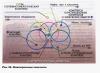
An electrical circuit includes copper and steel wires of equal length and diameter in series. Find the ratio of the amounts of heat released in these wires.
Consider a wire of length L and diameter d, made of a material with resistivity p. The wire resistance R can be found using the formula
Where s= is the cross-sectional area of the wire. At current strength I, during time t, the amount of heat Q is released in the conductor:
In this case, the voltage drop across the wire is equal to:
Copper resistivity:
p1=0.017 μOhm*m=1.7*10 -8 Ohm*m
steel resistivity:
p2=10 -7 Ohm*m
since the wires are connected in series, the current strengths in them are the same and during time t the amounts of heat Q1 and Q2 are released in them:
There is a circular coil with current in a uniform magnetic field. The plane of the coil is perpendicular to the field lines. Prove that the resultant forces acting on the circuit from the magnetic field are zero.
Since the circular coil with current is in a uniform magnetic field, it is acted upon by the Ampere force. In accordance with the formula dF=I, the resulting ampere force acting on a current-carrying coil is determined by:
Where integration is carried out along a given circuit with current I. Since the magnetic field is uniform, vector B can be taken out from under the integral and the task will be reduced to calculating the vector integral. This integral represents a closed chain of elementary vectors dL, so it is equal to zero. This means F=0, that is, the resulting Ampere force is zero in a uniform magnetic field.
A short coil containing 90 turns with a diameter of 3 cm carries current. The strength of the magnetic field created by the current on the axis of the coil at a distance of 3 cm from it is 40 A/m. Determine the current in the coil.
Considering that magnetic induction at point A is a superposition of magnetic inductions created by each turn of the coil separately:

To find the B turn, we use the Biot-Savart-Laplace law.
Where, dBturn is the magnetic induction of the field created by the current element IDL at the point determined by the radius vector r. Let us select the element dL at the end and draw the radius vector r from it to point A. We will direct the dBturn vector in accordance with the gimlet rule.
According to the principle of superposition:
Where integration is carried out over all elements of the dLturn. Let us decompose dBturn into two components dBturn(II) - parallel to the plane of the ring and dBturn(I) - perpendicular to the plane of the ring. Then