If two flat, parallel electrodes are placed in a vacuum and connected to a source of electromotive force, then an electric field is formed in the space between the electrodes, the lines of force of which will be straight, parallel to each other and perpendicular to the surfaces of both electrodes.
On rice. 1 the letter a denotes the electrode connected to the “+” of the battery E B, and the letter k denotes the electrode connected to the “-” battery E B. If a charge -e is placed in such an electric field, which does not change the configuration of the field, then this charge will be acted upon force F, equal to the product of the field strength E and the amount of charge -e:
The minus sign indicates that the force F acting on the negative charge -e and the field strength E have opposite directions. For a uniform electric field, the product of the intensity E and the distance between the electrodes h is equal to the applied potential difference between the electrons:
Eh = U to -U a,
and U k and U a are the potentials of the electrodes k and a.
The work done by the field when moving an electron from one electrode to another will accordingly be equal to
A = Fh = e(U a - U k). (3)
Electron acquires kinetic energy and will move from electrode to to electrode a uniformly accelerated. The speed υ with which the electron reaches electrode a can be determined from the equality
![]()
![]() (4)
(4)
where m is the electron mass; υ a is the speed of the electron at electrode a; υ k - electron speed at the electrode k ( initial speed).
If we neglect the initial speed of the electron, then formula (4) can be simplified: by replacing the ratio of the electron charge to its mass numerical value and expressing the potentials in volts and the speed in m/sec, we get
![]() (5)
(5)
The time it takes an electron to travel the distance h between the electrodes is determined by the formula
where υ av =υ a -υ k /2 is the average speed of the electron.
If the electron moves in a direction coinciding with the direction of the electric field strength vector E, then the direction of movement will be opposite to the force acting on the electron, and it will expend the previously acquired kinetic energy. Thus, an electron can move towards the action of the field only if it has a certain initial speed, i.e., a certain amount of kinetic energy.
A practically uniform electric field in electric vacuum devices is extremely rare. In a non-uniform field, the intensity varies from point to point both in magnitude and direction. Therefore, the force acting on the electron also changes both in magnitude and direction.
 |
In electric vacuum devices, along with an electric field, to influence electron movement A magnetic field is also used. If the electron is at rest or if it moves parallel to the magnetic field line, then no force acts on it. Therefore, when determining the interaction of a moving electron and a magnetic field, only the velocity component perpendicular to the magnetic field lines should be taken into account. The force F acting on the electron is always perpendicular to the magnetic field strength vector and the electron velocity torus ( rice. 3). Rice. 3. Movement of an electron in a magnetic field. |
The direction of the force F can be determined by the “gimlet rule”: if the handle of the gimlet is rotated in the direction from the vector H to the electron velocity vector υ in the shortest angular direction, then forward motion The gimlet coincides with the direction of force F. Since the action of force F is always perpendicular to the direction of motion of the electron, this force cannot do work and only affects the direction of its motion. The kinetic energy of the electron remains the same; it moves at a constant speed. The magnitude of the force F is determined by the formula
where e is the electron charge; H - magnetic field strength; υ p is the component of the electron velocity perpendicular to the field H. The force F imparts to the electron a significant centripetal acceleration, while changing the trajectory of its movement. The radius of curvature of the electron trajectory is determined by the formula
![]() (8)
(8)
where H - in oersteds; υ p - in volts; r - in centimeters.
By changing the magnetic field strength, you can change the radius of the electron trajectory. If the electron also has a velocity component along power lines magnetic field, then the electron trajectory will be helical with a constant pitch.
Often an electron moves in a space in which there are simultaneously electric and magnetic fields. In this case, depending on the magnitude and direction of the initial velocity of the electron, as well as on the strength of the electric and magnetic fields, the electron trajectory will have a different shape.
As soon as the electron exhibits some speed, a transverse deflection force F arises, and the greater the speed of the electron c, which it acquires due to interaction with the electric field, the greater the force F becomes. At point B, the electron moves perpendicular to the electric field lines fields. At this point the electron has highest speed, and therefore the maximum kinetic energy.Further movement of the electron occurs under the influence of a magnetic field and an electric field that has become decelerating for it. At point C, all the kinetic energy previously stored by the electron will be spent on overcoming the braking electric field. The potential of point C is equal to the potential of point A. The electron, having described a cycloid trajectory, returns to its previous potential level.
Movement of electrons in a magnetic field.
In a magnetic field, moving electrons are acted upon by the Lorentz force, always directed perpendicular to the velocity vector. Therefore, electrons move in a circular arc. A magnetic field only changes the direction of motion of the electron.
For example, TV picture tubes use magnetic beam deflection, and an oscilloscope cathode ray tube uses electrostatic beam deflection.
2) Classification electronic devices. Electronic emission
Based on the medium in which electrons move, there are:
A) electronic vacuum devices– the source of free electrons is the phenomenon of electron emission;
b) ion gas-discharge devices- the source of free electrons is electron emission plus impact ionization of atoms and molecules
V) semiconductor (s/p) devices– electrons are released from the atom under the influence of various reasons(change in temperature, light, pressure) therefore concentration free media The charge can be significantly greater than in vacuum and gas-discharge devices, and this leads to smaller dimensions, weight and cost of semi-automatic devices.
Topic 1.1. Physics of phenomena in semiconductors.
1. Semiconductors, types of semiconductors by conductivity.
2. Contact of two semiconductors with different impurity conductivity.
2.1. Direct and reverse switching on p-n transition. Basic properties.
2.2. CVC p-n junction. Types of breakdown.
2.3. The influence of temperature on the p-n junction.
3. Contact between semiconductor and metal. Schottky barrier.
1. Semiconductors - these are substances that have electrical conductivity significantly depends on the temperature of illumination, pressure and impurity.
For example, with an increase in temperature by 1 degree Celsius, the resistance of a metal will increase by 0.4%, and that of a semiconductor will decrease by 4-8%.
Examples of semiconductors: germanium(Ge), silicon(Si), substances based India, gallium arsenide.
Types of semiconductors by conductivity:
A) intrinsic conductivity;
B) impurity conductivity;
A) Intrinsic conductivity represents the movement of free electrons and holes, the number of which is identical and noticeably depends on the temperature of illumination and pressure.
Intrinsic conductivity can be observed in a pure, unimpurity semiconductor.
An accepted pure semiconductor having only intrinsic conductivity call semiconductor i - type.
B) Impurity conductivity
There are two types of impurity conductivity:
- electronic impurity conductivity is obtained by adding impurities with a valence one unit greater than the valence of the semiconductor. Moreover, 4 of valence electrons Each impurity atom participates in the formation of bonds, and the fifth easily becomes free without the formation of a hole. Therefore, such semiconductors are dominated by free electrons.
Semiconductors in which free electrons predominate are called semiconductors n-type.
For example, Ge (germanium) + As (arsenic) – semiconductor n-type.
- hole impurity conductivity is obtained by adding impurities with a valence one less than the valence of the semiconductor. In this case, each impurity atom lacks one electron to complete the bond with the semiconductor atoms; therefore, the number of holes in the semiconductor predominates.
Semiconductors in which holes predominate are called semiconductors p-type .
For example, Ge + In (indium) is a semiconductor p-type.
2. The contact of two semiconductors with different impurity conductivity “n and p” - type, is called a “p-n” junction.
At the point of contact there is always an electric transition field (E per), directed from the “n” region to the “p” region.
|
d - thickness of the “p-n” junction
U к – contact voltage
Example: Ge d= (10 -6 ÷ 10 -8) m and U k = (0.2 to 0.3) V.
As the impurity concentration increases, d- decreases, and Uk increases.
2.1. Two ways to turn on a pn junction:
I.direct connection of p-n junction in the p-region plus, in n-region minus from the source, therefore, at E source< E пер прямой ток I пр =0 (на рисунке 6 отрезок ОД), при E ист >E lane creates a forward current I pr, which noticeably depends on the voltage, see Figure 3 and Figure 4.

The dependence of I on U is called current-voltage characteristic (volt-ampere characteristic).
The current-voltage characteristic of the p-n junction with direct connection is shown in Figure 4.

When switched on directly, the current is created by the main charge carriers - impurity conductivity.
II.Reverse switching of p-n junction shown in Figure 5.

To the p-region minus, to the n-region plus from the source, therefore, the electric field of the source (E source) is directed along the transition field and amplifies it, therefore the main charge carriers do not participate in the creation of the current.
The reverse current I arr is created by minority charge carriers, the number of which is small, therefore the reverse current I arr is less than I r
I rev<< I пр (в 1000 раз) – основное свойство p-n перехода.
When turned back on, the current is almost independent of voltage, see I-V characteristic in Figure 6.
With a sufficiently large reverse voltage (Urev max), a breakdown of the “p-n” junction occurs - this is a phenomenon noticeable increase in current (tens and hundreds of times).
There are two types of breakdowns:
- electrical breakdown, is observed only when switched back on, at a voltage Uob max, while under the influence of the electric field of the source, impact ionization of atoms occurs, therefore, pairs are formed: free electron - hole, the number of which is growing like an avalanche.
Electrical breakdowns occur when reverse current is less than or equal to the permissible transition current (Iper ≤ I add), therefore, electrical breakdown is considered reversible , this means that when the p-n voltage is removed, the junction restores its properties. The electrical breakdown in Figure 6 is the AB section
| |

- thermal breakdown occurs during direct or reverse switching, when the current exceeds the permissible values of I add. transition, at the same time the temperature increases, therefore, I increases, therefore, the temperature increases noticeably, etc. As a result, the p-n junction is destroyed, so thermal breakdown is called irreversible. The thermal breakdown in Figure 6 is the BG section.
2.3. With increasing temperature, the reverse current increases noticeably, because This is the intrinsic conductivity of the p/p, and the forward current remains almost unchanged. For example, when the temperature increases by 10 degrees Celsius, the reverse current increases by 2 ÷ 2.5 times.
This means there is a temperature tcr at which the reverse current becomes comparable to the forward current, i.e. thermal breakdown occurs. This temperature tcr, starting from which the intrinsic conductivity is comparable to the impurity conductivity, is called critical or degeneration temperature .
Although t cr depends on the concentration of impurity carriers, the determining parameter for it is the energy band gap. The wider the band gap, the larger tcr.
So, if for silicon tcr ≈ 330 ˚С, then for germanium the critical temperature will be lower (~ 100 ˚С).
There is also a lower temperature that affects the conductivity of a semiconductor - this temperature at which the impurity begins to exhibit its conductivity is called the activation temperature tact.
For all semiconductors, the activation temperature is the same: t act = -100 0 C.
Therefore, for all semiconductor devices there are operating temperature limits.
For example: Ge → t slave = – 60 to +75 0 C;
Si → t slave = -60 to +150 0 C.
3. There are 2 types of semiconductor and metal contacts:
- straightening– this contact is similar to a pn junction, but with less voltage loss and higher efficiency. The rectifying contact was first described by a German scientist in 1937 by W. Schottky, therefore the rectifying contact is called the Schottky barrier and is the basis of the Schottky diode, Schottky transistor.
- non-rectifying – conducts current equally when connected directly or reversely. Used to create metal leads and semiconductor devices.
Topic No. 2. Semiconductor devices
1. Classification of semiconductor devices;
2. Semiconductor diodes: zener diode, varicap, photodiode, tunnel diode;
2.1. Device, switching principle, operation, main property, UGO, application;
3. Bipolar transistor;
3.1. Types, device, principle of inclusion, operation, main property, UGO, application;
3.2. Three switching schemes;
3.3. Main parameters and characteristics;
3.4. Marking;
4. Field-effect transistors;
4.1. Types, device, principle of inclusion, operation, main property, UGO, application;
5. Unijunction transistors.
Some electronic devices use the influence of a magnetic field on electrons moving in it.
In § 3-2, c, expression (3-6) was obtained for the force with which a uniform magnetic field acts on an electron moving perpendicular to the direction of the field. The magnitude of this force is proportional to the product of magnetic induction B, the charge of the electron and the speed of its movement v in the direction perpendicular to the direction of the field, i.e. It was also established there that the direction of this force is determined by the left-hand rule.
From the force expression (3-6) it follows that when the force is , i.e., the magnetic field does not act on a stationary electron. Since the direction of the force F is perpendicular to the direction of the speed of the electron, the work done by it is zero. Thus, the energy of the electron and the magnitude of its speed remain unchanged, and only the direction of motion of the electron changes.
If the electron is affected only by a magnetic field, then it will move along a circle of radius (Fig. 13-4), located in a plane perpendicular to the direction of zero.
The force F is centripetal and is balanced by the centrifugal force of the electron.
Since these forces are equal, we can write
![]()
where is the radius of a circle determined?
The ratio of the mass of an electron to its charge is constant, therefore, the radius of the circle is proportional to the speed of the electron and inversely proportional to the magnetic induction of the field.

Rice. 13-4. The motion of an electron in a magnetic field at an initial speed v in a plane perpendicular to the magnetic induction vector of the field.

Rice. 13-5. The movement of an electron in a magnetic field with an initial speed directed at an acute angle to the magnetic induction vector of the field.
If the initial velocity of the electron is not perpendicular to the direction of the field, then it should be decomposed into two components: normal, i.e. perpendicular to the direction of the field and longitudinal, i.e. coinciding in direction with the field (Fig. 13-5).
The first component of the velocity causes the electron to move in a circle in a plane perpendicular to the direction of the field, the second component causes the electron to move uniformly and rectilinearly in the direction of the field, thus the electron moves along a helical line (Fig. 13-5).
Purpose of the work.
Devices and accessories: e
Introduction
e, speed of light With, Planck's constant h Kl∙kg -1 .
Magnetic field. IN B B q, moving at speed V
F l = q∙[ V∙B] or F l = |q|VB∙sinα(1)
where α – V IN .
». B
q> I
 Fig.1
Fig.1
q>q< 0) current direction I and speed V V B r determined from the condition
![]() , (2)
, (2)
where α is the angle between the vectors V And B .
In case α = 90 0 , sinα
Δ A = F l. Δ r
or Δ A = F l. Δ rcosβ, (4)
Where β F Δ r .
 F
l Δ r
, β
= 90 0 and cosβ
F
l Δ r
, β
= 90 0 and cosβ
r
V directed at an angle α to power lines IN V // = V∙cosα and uniform

V ┴ = V∙sinα.
V //
h = VTcos, (7)
Substituting this expression for T in (7), we get
![]() . (8)
. (8)
B .
Electric field. On point charge q, E , force acts
F= q E , (9)
Direction of force F E E .
According to Newton's second law F= m a
q E = (10)
X at speed V

Charge movement along the axis X x= x 0 + Vt(x 0 – initial coordinate, t– time), V= const, x 0 = 0. ℓ equals .
Movement along the axis Y , E y = V y = V 0 y + at. U , Where WITH− t= 0) V 0 y = 0 we get C = 0. .
Y according to the formula ![]() .
.
U,
IN E , then the resulting force F
F Em = q E + q[V∙B ]. (11)
UVV << скорости света c ) having the form
Where e m
From (12) the electron speed
![]() . (13)
. (13)
U, B r
Experimental setup


3 – power supply IP1 Helmholtz coils; 4 – Helmholtz coils; 5 - power supply IP2 cathode ray tube.
Functional parts of the experimental setup and their connection diagrams
 Helmholtz coils(Helmholtz rings) are two coaxial ring conductors of the same radius with n number of turns, located in parallel planes coaxially, such that the distance between them is equal to the radius of the rings (Fig. 8).

In Fig. Figure 9 shows a diagram of connecting Helmholtz coils to a power source IP1 .
When current is passed through the coils, a magnetic field is generated in the space between them, characterized by a high degree of uniformity. It is the result of a superposition of magnetic fields induced by each current-carrying turn of the ring conductor and the entire system of two ring conductors (Fig. 8).
The magnetic field induction in the center of a ring current-carrying conductor containing one turn is expressed by the formula
Where R– radius of curvature of the conductor, I– current strength in it, µ – magnetic permeability, µ 0 – magnetic constant (µ 0 = 4π·10 -7 H/m).
The magnitude of the magnetic field induction on the axis of the coils is proportional to the current I, flowing in the winding of each of the ring conductors and the number of turns in them n. Theoretical calculation of the magnetic induction field of Helmholtz coils using the Biot-Savart-Laplace law and the principle of superposition on the axis X at the center of the system leads to an adapted formula for calculation IN, used in this work
![]() . (15)
. (15)
Where R– radius of the ring conductor, µ 0 = 4π·10 -7 H/m (magnetic constant).
Figure 10 shows the distribution of magnetic field induction in the space between the Helmholtz coils along the axis x, coinciding with the axis of symmetry of the coils. The dotted line shows the distribution of magnetic fields created by each of the ring conductors.

The inhomogeneity of the generated field with appropriate adjustment of the coils may not exceed 5%.
Cathode ray tube (CRT ) used in the experimental setup is shown in Fig. 11. The photo (top view) also illustrates its location in the space between the Helmholtz coils in the region of a uniform magnetic field. CRT is a beam tetrode in a spherical glass flask with a vacuum. The flask contains an electron gun - an indirectly heated cathode, mounted on a metal cross-arm with jumpers. To visualize the electron beam, a glass bulb is filled with hydrogen at low pressure.

Fig. 11. Cathode ray tube with Helmholtz coils (top view):
1 – electron gun; 2 – traverse with jumpers, used as a scale for estimating the radius of the electron trajectory;
3 – Helmholtz coils.
The electrons emitted by the cathode due to thermionic emission are focused by the electrodes of the electron beam gun in the form of a beam and move along a straight trajectory vertically upward. When voltage is applied to the Helmholtz coils from a power source IP1 in the field of accommodation CRT, a uniform magnetic field is created. The trajectory of the electron beam changes from straight to circular.

The effect is observed visually by a weak bluish glow inside the glass bulb, corresponding to the trajectory of the electron beam. The diameter of the visualized electron trajectory is estimated using a crossbar located in the flask with several jumpers coated with a phosphor (Fig. 12).
Figure 13 shows the connection diagram to the power source IP2
cathode ray tube indicating the range of changes in source parameters.


Rice. 14. Power supply for Helmholtz coils ( IP1 ) (photo of the front panel).

Rice. 15. Power supply for cathode ray tube ( IP2 ) (photo of the front panel).
Work order
NOTE 1.
All devices and functional elements of the installation are connected by connecting cords.
DO NOT TOUCH!
ATTENTION.
When performing work, it is necessary to strictly observe the safety regulations established at the workplace and in the laboratory.
ATTENTION.
| ALLOWABLE RANGES FOR CHANGING PARAMETERS OF POWER SOURCES. IP1 CURRENT IN HELMHOLTZ COILS from 0 to 3 A. IP2 ACCELERATING VOLTAGE CRT from 100 to 300 V |
ATTENTION.
Measurements must be carried out in a darkened room in order to observe the trajectory of the electron beam.
NOTE 4.
On the experimental setup, it is also possible to measure the radius of the electron beam trajectory using the third scale jumper from the left, located in a glass flask, for recording CRT. It corresponds to the radius of the electron beam r 3= 0.03 m (Fig. 12).
14. These measurements should be carried out at the request of the teacher. Repeat steps 11 and 12 several times, observing the intersection of the electron beam with the third jumper.
15. Measurement data of the corresponding pairs of characteristics: accelerating voltage U and current in the coils I and for each experiment at r 3= 0.03 m enter into the table 2.
16. Switch off the measuring unit.
Shutdown order:
a) use the adjustment knobs to reduce the current in the Helmholtz coils to zero (turn to the extreme left position). On IP1 Set the left and right knobs to 0.
b) use the adjustment knobs to reduce the accelerating voltage of the cathode ray tube to zero (turn to the extreme left position on IP2 2nd and 3rd handles).
c) turn off the power sources IP1 And IP2 (toggle switches on the rear panel).
Table 1
| r 1= 0.05 m | ||||||||
| No. | U, B | I,A | B∙ 10 -6 , T | ∙10 11, C/kg | ||||
| () cf. , C/kg | ||||||||
| r 2 = 0.04 m | ||||||||
| No. | U,B | I,A | IN∙10 -6 , T | ∙10 11 C/kg | ||||
| () cf. C/kg | ||||||||
Table 2
| r 3 = 0.03 m | ||||
| N. p/p | U, B | I, A | IN∙10 -6 , T | ∙10 11 C/kg |
| () cf. C/kg |
References
1. Yavorsky B.M., Detlaf A.A. Physics course. – M.: Publishing house “Academy”, 2005 and onwards. – 720 s.
2. Trofimova T.I. Physics course. – M.: Higher School, 2004 and onwards. – 544 p.
3. Savelyev I.V. Course of general physics in 3 volumes. – M.: Astrel AST, 2007 and onwards.
Zakharova T.V. (general ed.) Physics. Collection of tasks in test form, part 2. – M.: MIIT, 2010 – 192 p.
MOVEMENT OF ELECTRONS IN A MAGNETIC FIELD
Purpose of the work. Determination of the specific charge of an electron along the known trajectory of an electron beam in electric and alternating magnetic fields.
Devices and accessories: e experimental setup of the "PHYWE" brand from HYWE Systems GmbH & Co. (Germany) consisting of: cathode ray tube; Helmholtz coils (1 pair); universal power supply (2 pcs.); digital multimeter (2 pcs.); multi-colored connecting cords.
Introduction
Specific charge of an elementary particle is the ratio of a particle's charge to its mass. This characteristic is widely used to identify particles, as it allows one to distinguish from each other different particles that have the same charges (for example, electrons from negatively charged muons, pions, etc.).
The specific charge of an electron refers to fundamental physical constants such as the charge of an electron e, speed of light With, Planck's constant h etc. Its theoretical value is = (1.75896 ± 0.00002)∙10 11 Kl∙kg -1 .
Numerous experimental methods for determining the specific charge of particles are based on studies of the characteristics of their motion in a magnetic field. Additional possibilities are provided by using the configuration of magnetic and electric fields and varying their parameters. In this work, the specific charge of an electron is determined on an experimental installation of the “PHYWE” brand, made in Germany. In it, to study the trajectories of electron motion in a magnetic field, a method is implemented that is based on a combination of the possibilities of varying the parameters of uniform magnetic and electric fields with their mutually perpendicular configuration. This manual was developed using the documentation supplied with the installation.
Magnetic field. Experiments show that the magnetic field affects charged particles moving in it. The force characteristic that determines this effect is magnetic induction - a vector quantity IN .The magnetic field is depicted using lines of magnetic induction, the tangents to which at each point coincide with the direction of the vector B . For a uniform magnetic field, the vector B constant in magnitude and direction at any point in the field. Force acting on the charge q, moving at speed V in a magnetic field, was determined by the German physicist G. Lorentz (Lorentz force). It is expressed by the formula
F l = q∙[ V∙B] or F l = |q|VB∙sinα(1)
where α – the angle formed by the velocity vector V moving particle and magnetic field induction vector IN .
To a stationary electric charge the magnetic field has no effect. This is its significant difference from the electric field.
The direction of the Lorentz force is determined using the left-hand rule ». If the palm of the left hand is positioned so that the vector enters it B , and point four outstretched fingers along
direction of movement of positive charges ( q>0), coinciding with the direction of the current I(), then bent thumb
Fig.1
will show the direction of the force acting on positive charge (q>0) (Fig. 1). In the case of negative charges ( q< 0) current direction I and speed V the movements are opposite. The direction of the Lorentz force is determined by the direction of the current. Thus, the Lorentz force is perpendicular to the velocity vector, so the velocity modulus will not change under the influence of this force. But when constant speed, as follows from formula (1), the value of the Lorentz force also remains constant. From mechanics it is known that constant force, perpendicular to the speed, causes movement in a circle, that is, it is centripetal. In the absence of other forces, according to Newton's second law, it gives the charge a centripetal or normal acceleration. The trajectory of a charge in a uniform magnetic field at V B is a circle (Fig. 2), the radius of which r determined from the condition
![]() , (2)
, (2)
where α is the angle between the vectors V And B .
In case α = 90 0 , sinα= 1 from formula (2), the radius of the circular trajectory of the charge is determined by the formula
Work done on a moving charge in a magnetic field constant force Lorentz, equal
Δ A = F l. Δ r
or Δ A = F l. Δ rcosβ, (4)
Where β – angle between the direction of the force vectors F l. and the direction of the displacement vector Δ r .
Since the condition is always satisfied F
l Δ r
, β
= 90 0 and cosβ= 0, then the work done by the Lorentz force, as follows from (4), is always equal to zero. Hence, absolute value the speed of the charge and its kinetic energy when moving in a magnetic field remain constant.
Rotation period (time of one full turn), is equal to
Substituting in (5) instead of the radius r its expression from (3), we obtain that the circular motion of charged particles in a magnetic field has important feature: the orbital period does not depend on the particle energy, it depends only on the magnetic field induction and the reciprocal of the specific charge:
If the magnetic field is uniform, but the initial speed of the charged particle V directed at an angle α to power lines IN , then the movement can be represented as a superposition of two movements: uniform rectilinear in a direction parallel to the magnetic field with speed V // = V∙cosα and uniform
rotation under the influence of the Lorentz force in a plane perpendicular to the magnetic field at a speed V ┴ = V∙sinα.
As a result, the trajectory of the particle will be a helical line (Fig. 3).
Helix pitch equal to the distance, passed by a charge along the field with a speed V // for the time equal to the period rotation
h = VTcos, (7)
Substituting this expression for T in (7), we get
![]() . (8)
. (8)
The spiral axis is parallel to the magnetic field lines B .
Electric field. To a point charge q, placed in an electric field characterized by a voltage vector E , force acts
F= q E , (9)
Direction of force F coincides with the direction of the vector E , if the charge is positive, and opposite E in case of negative charge . In a uniform electric field, the intensity vector at any point in the field is constant in magnitude and direction. If the motion occurs only along the lines of force of a uniform electric field, it is uniformly accelerated rectilinear.
According to Newton's second law F= m a the equation of motion of a charge in an electric field is expressed by the formula
q E = (10)
Let's assume that the point negative charge, moving initially along the axis X at speed V , falls into a uniform electric field between the plates flat capacitor, as shown in Fig. 4.
Charge movement along the axis X is uniform, its kinematic equation x= x 0 + Vt(x 0 – initial coordinate, t– time), V= const, x 0 = 0. Time of flight of the charge of a capacitor with the length of the plates ℓ equals .
Movement along the axis Y determined by the electric field inside the capacitor. If the gap between the plates is small compared to their length , edge effects can be neglected and the electric field in the space between the plates can be considered uniform ( E y = const). The movement of the charge will be uniformly accelerated V y = V 0 y + at. U acceleration is determined with formula (10). Having performed integration (10), we obtain , Where WITH− integration constant. At initial condition (t= 0) V 0 y = 0 we get C = 0. .
The trajectory and character of motion of a charged particle in a uniform electric field of a flat capacitor are similar to the similar characteristics of motion in a gravitational field of a body thrown horizontally. Deflection of a charged particle along the axis Y equals . Taking into account the character acting force it depends on according to the formula ![]() .
.
When a charge moves in an electric field between points that have a potential difference U, work is done by the electric field, as a result of which the charge acquires kinetic energy. In accordance with the law of conservation of energy
If a moving electric charge, in addition to a magnetic field with induction IN there is also an electric field with the intensity E , then the resulting force F , which determines its movement, is equal to the vector sum of the force acting from the electric field and the Lorentz force
F Em = q E + q[V∙B ]. (11)
This expression is called the Lorentz formula.
In this laboratory work the movement of electrons in magnetic and electric fields. All the relationships discussed above for arbitrary charge, are also valid for the electron.
We assume that the initial speed of the electron is zero. Getting into an electric field, the charge accelerates in it, and, having passed the potential difference U, acquires some speed V. It can be determined from the law of conservation of energy. In the case of non-relativistic speeds ( V << скорости света c ) having the form
Where e= –1.6∙10 -19 C – electron charge, m e = 9.1∙10 -31 kg – its mass.
From (12) the electron speed
Substituting it into (3), we obtain a formula for finding the radius of the circle along which the electron moves in a magnetic field:
![]() . (13)
. (13)
Thus, knowing the potential difference U, accelerating electrons as they move in an electric field to non-relativistic speeds, induction of a uniform magnetic field B, in which these electrons move, describing a circular trajectory, and experimentally determining the radius of the specified circular trajectory r, you can calculate the specific charge of an electron using the formula
Experimental setup
A photo of the measuring stand is shown in Fig. 5.
In Fig. Figure 6 shows a photo of the experimental setup of the “PHYWE” brand.
In Fig. Figure 7 shows the main components of the experimental setup with designations of functional parts.
Fig.7. Experimental setup:
1 – cathode ray tube; 2, 6 – digital multimeters;
3 – power supply IP1 Helmholtz coils; 4 – Helmholtz coils; 5 - source p
Below are the conditions of the problems and scanned solutions. If you need to solve a problem on this topic, you can find a similar condition here and solve yours by analogy. The page may take some time to load due to the large number of images. If you need problem solving or online help in physics, please contact us, we will be happy to help.
The movement of a charge in a magnetic field can occur in a straight line, in a circle, or in a spiral. If the angle between the velocity vector and the magnetic field lines is not zero or 90 degrees, the charge moves in a spiral - it is acted upon by the magnetic field by the Lorentz force, which gives it centripetal acceleration.
A particle, accelerated by a potential difference of 100 V, moves in a magnetic field with an induction of 0.1 T in a spiral of radius 6.5 cm with a step of 1 cm. Find the ratio of the particle's charge to its mass.
An electron flies at a speed of 1 mm/s into a magnetic field at an angle of 60 degrees to the lines of force. Magnetic field strength 1.5 kA/m. Find the radius and pitch of the spiral along which the electron will move. 
An electron moves in a magnetic field with an induction of 100 μT in a spiral with a radius of 5 cm and a step of 20 cm. Find the speed of the electron. 
An electron, accelerated by a potential difference of 800 V, moves in a magnetic field with an induction of 4.7 mT in a spiral with a step of 6 cm. Find the radius of the spiral. 
A proton, accelerated by a potential difference of 300V, flies into a magnetic field at an angle of 30 degrees to the lines of force. Magnetic field induction 20 mT. Find the radius and pitch of the spiral along which the proton will move. 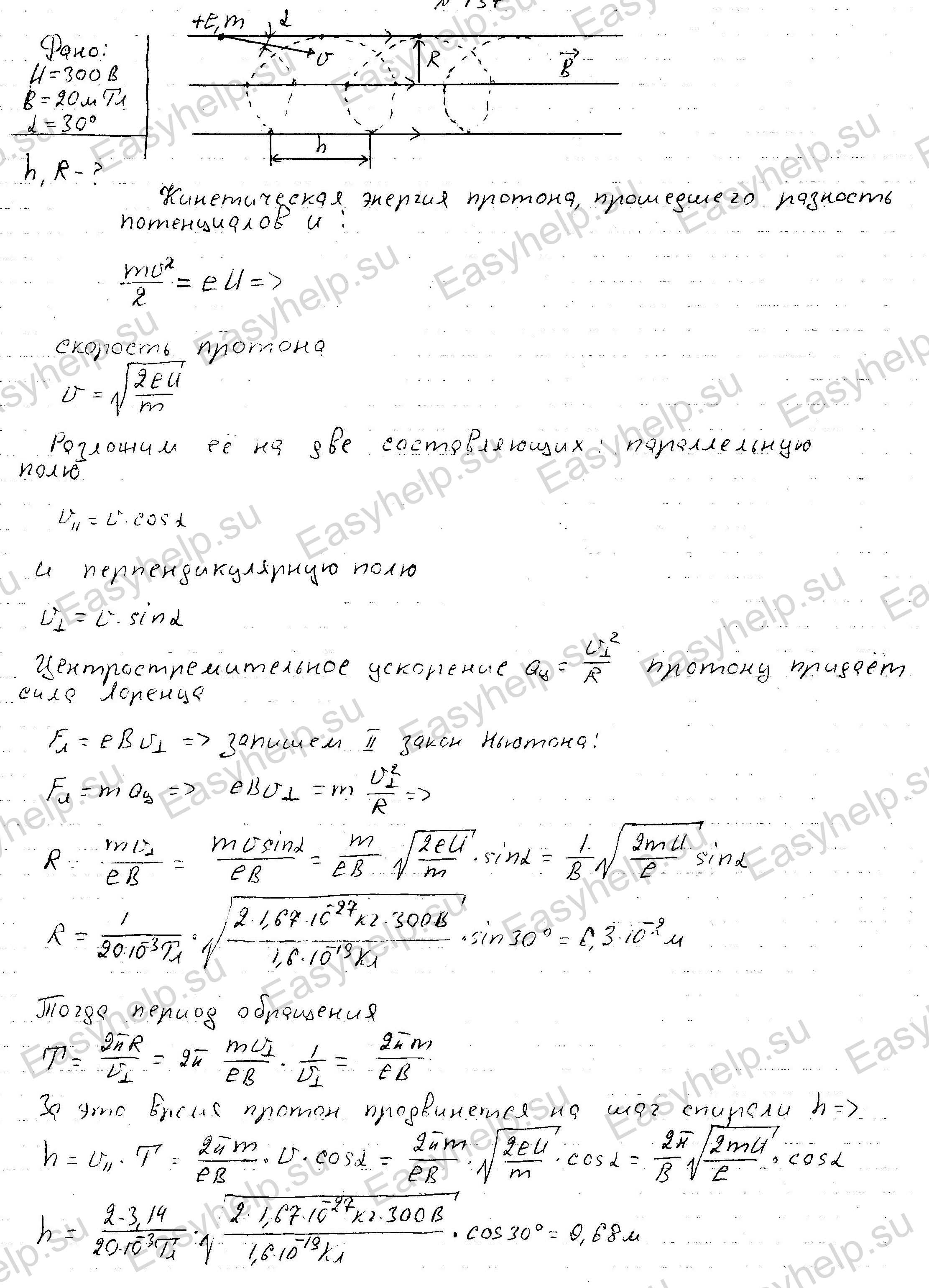
An electron, accelerated by a potential difference of 6 kV, flies into a magnetic field at an angle of 30 degrees to the lines of force. Magnetic field induction 13 mT. Find the radius and pitch of the spiral along which the electron will move. 
An alpha particle, accelerated by a potential difference U, flies into a magnetic field at an angle to the field lines. Magnetic field induction 50 mT. The radius and pitch of the spiral - the trajectory of the particle - are 5 cm and 1 cm, respectively. Determine the potential difference U. 


An electron flies at a speed of 1 mm/s into a magnetic field at an angle of 30 degrees to the lines of force. Magnetic field induction 1.2 mT. Find the radius and pitch of the spiral along which the electron will move. 
An electron flies at a speed of 6 mm/s into a magnetic field at an angle of 30 degrees to the lines of force. Magnetic field induction 1.0 mT. Find the radius and pitch of the spiral along which the electron will move. 
An electron moves in a magnetic field with an induction of 5 mT in a spiral with a pitch of 5 cm and a radius of 2 cm. Determine the speed and kinetic energy of the electron and the angle between the vectors of the electron speed and the magnetic induction of the field.