Let us find the connection between the optical characteristic and the distances that determine the position of the object and its image.
Let the object be a certain point A located on the optical axis. Using the laws of light reflection, we will construct an image of this point (Fig. 2.13).
Let us denote the distance from the object to the pole of the mirror  (AO), and from pole to image
  (OA).
(OA).
Consider the triangle APC, we find that 
From the triangle APA, we obtain that  . Let us exclude the angle from these expressions
  , since it is the only one that does not rely on OR.
 ,
, or
or
 (2.3)
(2.3)
Angles ,,are based on OR. Let the beams under consideration be paraxial, then these angles are small and, therefore, their values in radian measure are equal to the tangent of these angles:
 ;
;
 ;
; , where R=OC, is the radius of curvature of the mirror.
Let us substitute the resulting expressions into equation (2.3)


Since we previously found out that the focal length is related to the radius of curvature of the mirror, then
 (2.4)
(2.4)
Expression (2.4) is called the mirror formula, which is used only with the sign rule:
Distances  ,
, ,
, are considered positive if they are counted along the ray, and negative otherwise.
Convex mirror.
Let's look at several examples of constructing images in convex mirrors.


The focus of a convex mirror is imaginary. Convex mirror formula
 .
.
The sign rule for d and f remains the same as for a concave mirror.
The linear magnification of an object is determined by the ratio of the height of the image to the height of the object itself
 . (2.5)
Thus, regardless of the location of the object relative to the convex mirror, the image always turns out to be virtual, straight, reduced and located behind the mirror. While the images in a concave mirror are more varied, they depend on the location of the object relative to the mirror. Therefore, concave mirrors are used more often.
Having considered the principles of constructing images in various mirrors, we have come to understand the operation of such various instruments as astronomical telescopes and magnifying mirrors in cosmetic devices and medical practice, we are able to design some devices ourselves.
Specular reflection, diffuse reflection
Flat mirror.
The simplest optical system is flat mirror. If a parallel beam of rays incident on a flat surface between two media remains parallel after reflection, then the reflection is called mirror, and the surface itself is called a plane mirror (Fig. 2.16).


If the reflecting surface is rough, then the reflection wrong and the light scatters, or diffusely reflected (Fig. 2.19)

Diffuse reflection is much more pleasing to the eye than reflection from smooth surfaces, called correct reflection.
Lenses.
Lenses, like mirrors, are optical systems, i.e. capable of changing course light beam. Lenses can be different in shape: spherical, cylindrical. We will focus only on spherical lenses.

A transparent body bounded by two spherical surfaces is called lens.

Converging lenses . Focus A converging lens is the point at which rays parallel to the optical axis intersect after refraction in the lens. The focus of the converging lens is real. The focus lying on the main optical axis is called the main focus. Any lens has two main focuses: the front (from the side of the incident rays) and the back (from the side of the refracted rays). The plane in which the foci lie is called the focal plane. The focal plane is always perpendicular to the main optical axis and passes through the main focus. The distance from the center of the lens to the main focus is called the main focal length F (Fig. 2.21).

To construct images of any luminous point, one should trace the course of any two rays incident on the lens and refracted in it until they intersect (or intersect their continuation). The image of extended luminous objects is a collection of images of its individual points. The most convenient rays used in constructing images in lenses are the following characteristic rays:


Figure 2.25 demonstrates the construction of an image of point A of object AB.

In addition to the listed rays, when constructing images in thin lenses, rays parallel to any secondary optical axis are used. It should be borne in mind that rays incident on a collecting lens in a beam parallel to the secondary optical axis intersect the rear focal surface at the same point as the secondary axis.
Thin lens formula:
 , (2.6)
where F - focal length lenses; D is the optical power of the lens; d is the distance from the object to the center of the lens; f is the distance from the center of the lens to the image. The sign rule will be the same as for a mirror: all distances to real points are considered positive, all distances to imaginary points are considered negative.
The linear magnification given by the lens is
 , (2.7)
where H is the image height; h is the height of the object.
Diffusing lenses . Rays incident on a diverging lens in a parallel beam diverge so that their extensions intersect at a point called imaginary focus.
Rules for the path of rays in a diverging lens:

2) the beam traveling along the optical axis does not change its direction.
Diverging lens formula:

(the rule of signs remains the same).
Figure 2.27 shows an example of imaging in diverging lenses.
State educational institution of higher professional education "Siberian State Medical University of the Federal Agency for Health and Social Development"
(GOU VPO Siberian State Medical University of Roszdrav)
Department___________________________
Approved
At a department meeting
Protocol No.___from « «_______2009
Art. teacher Kolubaeva L.A.
LECTURE No. 2
"Optical systems"
Introduction:
Using laws geometric optics you can design a physical experiment. Obtain images of various objects that are impossible to observe by changing the optical path of rays.
1.Optical systems: reflective and refractive
2. Spherical mirrors and their optical characteristics.
3. Relationship between optical and geometric characteristics of mirrors.
4.Mirror reflection, diffuse reflection
5.Construction of images in mirrors and their characteristics.
6.Mirror formula and rule of signs. Magnifying images with a mirror
7. Lenses, optical axes, foci, vertices, focal surfaces. Thin lenses, optical center.
8. Refraction on a spherical surface.
Literature
1. Giancoli D. Physics. T.2; M. Mir, 1989
2. Myakishev T.Ya. Physics, Optics; M. Bustard, 2002
3. Savelyev I.V. Well general physics vol.3 M.ed. Bustard, 2003
Visual aids
Computer demonstrations
Presentations
Optical systems
Bodies or systems of bodies that transform the path of light rays are called optical systems.
If a diverging beam of rays is converted by an optical system into a converging beam, the image of the point obtained at the intersection of the converted rays is called real, and the optical systems are called collecting.
If a diverging beam of rays emerging from a luminous point is transformed by an optical system so that it remains divergent, the image of the point obtained at the intersection of the extensions of the transformed rays is called imaginary, and the system is called divergent. Virtual images are “optical ghosts” and cannot be observed on any screen, while real images actually exist and are easily observed.
Optical systems consisting of mirrors are reflective systems.
Optical systems consisting of lenses are refractive systems. Complex systems are used in practice.
Beam method for finding the location of an object.
We already know that in a homogeneous transparent medium, light travels in a straight line. Consider a point light source ( point is considered a source whose dimensions can be neglected compared to the distances at which its action is considered). The light rays emanating from this source are directed along the radii (see Fig. 2.1a). The ray method of finding the location of an object is based on the law of rectilinear propagation of light. If the directions of several rays emanating from a point source are known, then the position of this source can always be determined. You should simply continue at least two such rays in the direction opposite to their propagation, until they intersect. The point of their intersection is the position of the point source (see Fig. 2.1b).
When a beam of diverging rays enters the eye from a source, the lens of the eye automatically changes its shape so that the rays diverging from a point source are collected on the retina of the eye, thus we get an image of a point. This process gives the same information that we obtain by continuing the rays until they intersect.
The beam method of finding the location of an object is used when constructing images. Image a point source is the point at which rays or their extensions from this source intersect after passing through an optical system (mirror, prism, lens)
Spherical mirrors and their optical characteristics.

The vertex of the spherical segment O is called mirror pole. A straight line passing through the optical center of a mirror is called its optical axis. The optical axis passing through the pole of the mirror is called the main one, and the other optical axes are called secondary optical axes. According to the laws of reflection, the ray incident on a spherical mirror and the reflected ray make equal angles with the radius of curvature of the mirror and lie in the same plane with it. The main optical axis is distinguished from all other straight lines passing through the optical center only by the fact that it is the axis of symmetry of the mirror.
Concave mirror. Focus .

Reflection of a parallel beam of rays from a concave spherical mirror. Points O– optical center, P– pole, F– main focus of the mirror; OP– main optical axis, R– radius of curvature of the mirror.
The focus of a concave mirror is the point at which parallel rays incident on the mirror intersect after reflection.
The focus lying on the main optical axis is called the main focus. The focus lying on the secondary axis is called secondary. The foci of a concave mirror are real. The distance between the pole and the main focus is called the main focal length F. The geometric location of all foci is a part of the spherical surface called the focal surface.
The main focus of a convex mirror is imaginary. If a beam of rays parallel to the main optical axis falls on a convex mirror, then after reflection at the focus it is not the rays themselves that intersect, but their continuations (Fig. 2.4).

The principal focal length of a spherical mirror is related to the radius of curvature.
Spherical mirrors can give various images items. To construct an image of one point A, created by a spherical mirror, use any two of the three rays, shown in Fig. 29.13. Beam 1 from point A is drawn parallel to the main optical axis.
After reflection, it passes through the main focus of the mirror F. Beam 2 from point A is conducted through the main focus F. After reflection from the mirror, it goes parallel to the main optical axis of the mirror. Beam 3 is conducted through the spherical center C of the mirror. After reflection, he goes back to point A along toh straight.
Examples of images of objects created by spherical mirrors are shown in Fig. 29.14. Note that a convex mirror always gives a virtual image of objects.
Let's find out how to find the position of the image of the luminous point A, located on the main optical axis OS of the mirror (Fig. 29.15). Clear, that the image of the point should be on the same axes (explain why).

Let us draw an arbitrary ray AB from point A. At the point of its fall B we draw the radius NE. It is normal (perpendicular) to the surface of the mirror, therefore<1 = <2, что и определяет положение отраженного луча BA1. At point A1 you get the image of point A. The position of point A1 is uniquely determined by the position of point A itself. Therefore, points A and A1 are called conjugate.
Let us denote the distance AO by d, A1O by f and OC by R. For mirrors whose surface is a small part of the surface of the sphere, we can approximately assume that BA ≈ OA = d and BA1 ≈ OA1 = f. Because<1 = <2, то линия ВС в треугольнике ABA1 является биссектрисой угла АВА1, а это означает, что отрезки АС и A1C are proportional to the sides of triangle ABA1.
A1C/AC = BA1/BA, or (R-f)/(d-R) = f/d.
Let's transform the last relation:
Rd – fd = fd – Rf; Rf + Rd = 2fd.
After dividing by Rfd we get 1/d + 1/f = 2/R. Replacing R with its value, we get the formula conjugate points of the mirror:
1/d + 1/f = 1/F. (29.2)

This formula is valid for both concave and convex mirrors, but the numerical values of real quantities should be substituted with a plus, and imaginary quantities with a minus. For example, the main focal length of concave mirrors is taken with a plus sign, and for convex mirrors with a minus sign. A negative answer shows that the corresponding quantity is imaginary.
Optics
The branch of physics that studies light phenomena, elucidates the nature of light, establishes the properties of light, the laws of its radiation, propagation and interaction with matter is called optics.
Optics is divided into the following sections; photometry, geometric optics, physical optics.
Photometry Basics
Light is electromagnetic radiation perceived by the eye.
Luminous flux
To assess light energy by visual perception, the concept of luminous flux is used. The energy of light radiation can be assessed visually (with the eye) or with a photocell.
WITH  light flow characterizes (by visual sensation) light energy W, transferred through any surface in time t.
Luminous flux is power assessed visually.
Point light source
Emits light evenly in all directions. Its dimensions are much smaller than the distance at which its action is assessed.
T  forest corner
 .
.
An angle that exists around a point and subtends the entire area of the sphere (  ), is called the total solid angle:

If  , That
  1 Wed.
The power of light
 - energy characteristics of the light source.
E  The SI unit of luminous intensity is the candela (cd).
Luminous flux unit
 .
.
Expressed in lumens.
Full luminous flux

 , because
  Wed
Wed
Illumination(E)
Scalar physical quantity measured by the ratio of luminous flux to area S uniformly illuminated surface:
 .
.
Illuminance unit
In SI it is expressed in lux.
D  A lux meter is used to measure illumination.
Laws of illumination
1. Illumination of a surface by rays incident perpendicularly is proportional to the intensity of light I and inversely proportional to the square of the distance r 2 from source to illuminated surface:
E=I/r 2 .
2. The illumination of a surface is proportional to the cosine of the angle of incidence of the beam on this surface.
3 .
. .
.
Comparison of luminous intensity of two sources
To practically determine the light intensity of a source, a photometer is used, the diagram of which is shown in the figure.
If E 1 =E 2 then at distances r 1 and r 2
 ,
, .
.
Brightness
Characterizes the luminous flux that is emitted by a unit area in a perpendicular direction within a unit solid angle:
 ,
,
because  ,
,
 , Where S n- luminous surface. The SI unit of brightness is nit: 1 nit = 1 cd/m2.
Geometric optics
Geometric optics studies the laws of propagation of light energy in transparent media based on the concept of a light beam.
Rectilinear propagation of light occurs in a homogeneous medium.
Light ray - a line indicating the direction of propagation of light energy.
P  The linear propagation of light explains the formation of shadow and penumbra.
P  When the size of the source (luminous point) is small, only a shadow is obtained.
When the light source is large, unsharp shadows (umbra and penumbra) are created.
WITH  speed of light
Astronomical method for measuring the speed of light
M  Roemer's method (1676). When the Earth came very close to Jupiter (at a distance L 1), the time interval between two appearances of the satellite U 0 turned out to be 42 hours 28 minutes; When did the Earth move away from Jupiter? L 2, this period of time increased by 22 minutes. Roemer's explanation: the increase in time is due to the fact that the light travels an additional distance Δ l=L 2 –L 1. He determined that the speed of light is:
  = 300,000 km/s.
Laboratory method for measuring the speed of light
Fizeau's method (1849):
 = 313,000 km/s, where Z- number of teeth; ω
- angular velocity, L- distance from the gear to the mirror.
= 313,000 km/s, where Z- number of teeth; ω
- angular velocity, L- distance from the gear to the mirror.
According to modern data, in a vacuum c= (299792456.2 ± 0.8) m/s.
ABOUT  bird phenomena at the interface between two media
Reflection and absorption of radiation incident on a body depends on the type of substance, the state of the surface, the composition of the radiation and the angle of incidence.
ABOUT  light reflection
Diffuse, or scattered, reflection allows us to see bodies.

Mirror reflection.
Laws of light reflection
1. The incident beam and the reflected beam lie in the same plane perpendicular to the reflecting surface.
2. The angle of reflection of the beam is equal to the angle of its incidence ( α =γ ). Light rays have the property of reversibility.

AND  image in a plane mirror
AND  The image of any object in a plane mirror (virtual and direct) is equal in size to the object itself and is located symmetrically to the object relative to the mirror.
From many rays falling from a point S on the mirror MN, let us select three rays for simplicity: SO,SO 1 ,SO 2. Each ray will be reflected from the mirror at the same angle at which it hits the mirror. If we continue the reflected rays behind the mirror MN, then they will converge at the point S". The eye perceives them as if coming from a point S" and sees a dot there S.
Spherical mirror
WITH  A spherical mirror is the surface of a spherical segment that specularly reflects light. If the reflection comes from the inner surface of the segment, then the mirror is concave; if from the outside, then the mirror is convex.
A concave mirror is converging, a convex mirror is scattering.
Center ABOUT spheres - optical center mirrors Vertex WITH-pole.
O.B.-O.C.-R- radius of curvature of the spherical mirror.
Any straight line passing through the optical center is called the optical axis. The optical axis passing through the pole of the mirror is the main optical axis.
Diameter KM The circle enclosing the mirror is called the mirror opening.
Main focus of a spherical mirror
T  points F, at which rays parallel to the main optical axis intersect is called the main focus.
A concave mirror has a real focus, while a convex mirror has an imaginary focus, i.e., the continuation of the reflected rays intersect.
FS-focal lengthF. The concave one has it + F, at the convex – F.
The MM plane passing through the main focus of the mirror perpendicular to the main optical axis is called the focal plane.
E  If the secondary axes make a small angle with the main optical axis, then all the focal points of the mirror are located in the focal plane (for concave and convex mirrors).
ConnectionF WithR
L  uch A.A. 1, parallel to the main optical axis of the mirror, after reflection follows the path A 1 F. Connecting the dot A 1 , s ABOUT. From the laws of reflection it follows that2=3. Because A 1 A||O.C., then1 =2. Therefore,1 =3 and Δ A 1 FO isosceles, i.e. A 1 F=FO,A 1 F≈SF. Dot F divides R, i.e. divides OS in half:
  . From the laws of reflection it follows that the incident beam and the reflected beam in a spherical mirror are reversible. Rays incident on the mirror parallel to one of its secondary optical axes, after reflection, are collected at the focus of the mirror.
Spherical mirror formulas
 - for a concave mirror;
 - for a convex mirror, where d(in Fig. S.C.) is the distance from the object to the mirror, φ
(in Fig. S"C) - distance from the image to the mirror, F(in Fig. FC) - focal length.
- for a convex mirror, where d(in Fig. S.C.) is the distance from the object to the mirror, φ
(in Fig. S"C) - distance from the image to the mirror, F(in Fig. FC) - focal length.
Optical power of a spherical mirror

 ,
,
 ,
,
 , Where R- radius of the spherical mirror.
SI unit diopter:  .
.
Linear increase

 , Where h- height of the object, H- image height.
Image construction
To construct an image of point 1, any two of the three rays are used. Beam 1 is carried out parallel to the main optical axis. After reflection from the mirror, it passes through the main focus F.
Beam 2 carried out through F. After reflection from the mirror, it goes parallel to the main optical axis of the mirror.
Beam 3 carried out through the spherical center ABOUT mirrors After reflection he goes back to the point A along the same straight line. At the point of intersection of reflected rays from the mirror ( 1 ,2 ,3 ) we get an image of a point A.
Examples of constructing images of objects created by spherical mirrors
IN  depending on distance d, on which the object from the mirror is located, the following cases of construction for a concave mirror are possible:
at d= ∞ the image turns out to be a real point in focus;
at 2 F<d< ∞ изображение действительное, перевернутое, уменьшенное;
at d= 2F the image is real, inverted, equal to the object;
at F<d< 2F the image is real, inverted, enlarged;
at d=F the image does not exist (at infinity);
at d<F the image is virtual, direct, enlarged.
In a convex mirror, the image is always virtual, reduced, and direct.
P  refraction
At the interface between two media, the incident light flux is divided into two parts.
The Danish astronomer and mathematician W. Snell, before H. Huygens and I. Newton, experimentally discovered the law of light refraction in 1621:

 .
.
Absolute refractive index of a given medium  .
.
If  , That
  .
.
If  , That
  .
.
Let us apply Huygens' principle to derive the law of refraction of light.
R  propagation of incident and refracted rays. MM"- interface between two media; rays A 1 A And IN 1 IN incident rays; A.A. 2 and BB 2 refracted rays; α
- angle of incidence; β
- refraction angle:
propagation of incident and refracted rays. MM"- interface between two media; rays A 1 A And IN 1 IN incident rays; A.A. 2 and BB 2 refracted rays; α
- angle of incidence; β
- refraction angle:

Where  – constant value for two environments.
Thus,
 .
. ,
, .
.
The refraction of light obeys two laws:
1. The incident ray and the refracted ray lie in the same plane with a perpendicular drawn at the point of incidence of the ray to the interface between the two media;
2. The ratio of the sine of the angle of incidence to the sine of the angle of refraction for two given media is a constant value (for monochromatic light).
P  full reflection
P 
 With a further increase in the angle of incidence, the refracted beam disappears, and the brightness of the glass along the path of propagation of the reflected beam becomes the same as along the path of the incident beam.
Limit angle α
for media air - glass:  ,
, ,
, ,α
pr = 42°
,α
pr = 42°
For diamond ( n= 2,42)α pr = 25°, for media water ( n 2 = 1.33) - glass ( n 2 = 1,5):
 ,
, ,α
pr = 60°.
,α
pr = 60°.
The angle of incidence, which corresponds to a refraction angle of 90°, is called the limiting angle of incidence(α pr).
|
Turning prism. |
Rotating prism. |
|
|
|


A light guide is a cylindrical glass fiber coated with a sheath of transparent material with a refractive index lower than that of the fiber. Through multiple total reflections, light can be directed along a curved path.
Rotating and turning prisms are used in periscopes, binoculars, movie cameras, and often instead of mirrors.
Lenses
P  A body transparent to light, bounded by convex or concave refractive surfaces, is called a lens.
Converging (positive) lenses
Biconvex ( 1 ), Where ABOUT 1 ABOUT 2 - main optical axis, R 1 R 2 - radii of curvature of the surface, flat-convex ( 2 ), convex-concave ( 3 ).
Scattering (negative)
Concave-convex ( 4 ), biconcave ( 5 ), flat-concave ( 6 ).
Lenses whose centers are thicker than the edges are called converging, and those whose edges are thicker are called diverging.
These conditions are met if the refractive index of the glass from which the lens is made is greater than the refractive index of the medium in which the lens is used
Main foci and focal length of the lens
Dot F on the main optical axis, in which rays parallel to this axis intersect after refraction, is called the main focus.
A converging lens has real foci, a diverging lens has imaginary foci, OF- focal length. It is designated by the letter F. At the converging lens + F, for the scattering one - F.
A plane that is perpendicular to the main optical axis of the lens, and also pass! through its main focus, called focal:M 1 M 2 and M 3 M 4 .
P  side focus F" is a point on the focal plane M 3 M 4 in which rays incident on the lens parallel to the secondary axis are collected
Lens power  .
.
The SI unit of lens power is diopter. 
The optical power of a lens is determined by the curvature of its surface, as well as the refractive index of its substance relative to the environment:  , Where R 1 and R 2 - radii of the spherical surfaces of the lens; n- relative refractive index.
Derivation of the thin lens formula
AND  from the similarity of triangles shaded equally, it follows
 And
And 
where  ,df=dF+Ff,
df=F(d+f), .
.
or 
Where d- distance of the object from the lens; f- distance from the lens to the image; F- focal length. The optical power of the lens is:  .
.
When calculating, the numerical values of real quantities are always substituted with a “plus” sign, and imaginary quantities with a “minus” sign.
Linear increase
 .
.
AND  from the similarity of the shaded triangles it follows
 ,
, .
.
Constructing images of a luminous point located on the main optical axis of the lens
1 . A point in a converging lens S is between the main focus and the point ABOUT, i.e. d
<F. Let's draw a secondary axis O.A. parallel to an arbitrary ray S.A., and then straight AA 1 until it intersects with the main optical axis at the point S 1. A ray traveling along the main axis passes through the lens without refraction, so the image of a point S will be on the main axis at the point of intersection with the line AA 1 .
. A point in a converging lens S is between the main focus and the point ABOUT, i.e. d
<F. Let's draw a secondary axis O.A. parallel to an arbitrary ray S.A., and then straight AA 1 until it intersects with the main optical axis at the point S 1. A ray traveling along the main axis passes through the lens without refraction, so the image of a point S will be on the main axis at the point of intersection with the line AA 1 .
2
 . In a diverging lens, a point S is behind the main focus, i.e. d>F. Since all rays after refraction in the lens converge at a point S 1 then it is enough to establish where the two rays intersect. Let's find the path of an arbitrary ray S.A. after the lens. To do this from the point ABOUT let's draw the secondary optical axis parallel to the beam S.A.. It will intersect the focal plane at the point A 1. Line drawn through points A And A 1 sets the path of the ray SA after refraction in the lens. Continuing straight A.A. 1 until it intersects with the main optical axis, we get an image S 1 points S.
Converging lens
The point is located on the secondary optical axis. The lens creates its image on the same axis.
The image is valid.
The image is imaginary (for a converging lens and a diverging one).

AND  real image, reduced, inverted.
The image is virtual, upright, enlarged.

diverging lens
A diverging lens always produces a virtual, direct, reduced image.

|
The image is virtual, upright, reduced. |
Virtual image |
Eye
The eye is 90% of the information, a system of lenses. Eye diameter ~ 23 mm.
WITH  composed of sclera 1
(protective shell made of elastic tissue), corneas 2
, cameras 3
(a cavity filled with clear liquid), choroid 4
, iris 5
, holes 6
(pupil d from 2 to 8 mm), lens 7
(n=1.44), muscles that change the optical properties of the eye 8
, transparent gelatinous mass 9
(fundus), retina 10
(7 million cones, 130 million rods, which react differently to light of different frequencies), branches of the optic nerve 11
.
composed of sclera 1
(protective shell made of elastic tissue), corneas 2
, cameras 3
(a cavity filled with clear liquid), choroid 4
, iris 5
, holes 6
(pupil d from 2 to 8 mm), lens 7
(n=1.44), muscles that change the optical properties of the eye 8
, transparent gelatinous mass 9
(fundus), retina 10
(7 million cones, 130 million rods, which react differently to light of different frequencies), branches of the optic nerve 11
.
ABOUT  main properties of the eye
Accommodation is a property of the eye that provides clear perception of objects at different distances. The main focus of the eye changes from 16 to 13 mm. The optical power of the eye is from 60 to 75 diopters.
Ultimate angle of view φ 0 =1´. As the object approaches, the angle of view increases φ 0, under which we see two close points of the object.
Adaptation - adaptable to different lighting conditions: d sp from 2 to 8 mm, S SP changes 16 times.
Field of view. Axis OH 150°, along the axis OY 125°.
Spectral sensitivity from 380 to 760 nm. Greatest sensitivity λ = 555 nm (green).
ABOUT  visual acuity is the ability of the eye to separately distinguish two close points.
Best vision distance d 0 = 250mm. The eye sees distant objects without strain.
Eye defects
G  the eye cannot create a sharp image on the retina.
Farsightedness- a visual defect consisting in the fact that the image of an object in a relaxed state of the eye is obtained behind the retina.
When viewing close objects, the limit of accommodation is exhausted at a distance of more than 25 cm. Corrected by wearing glasses with converging lenses, Where F G- focal length of the eye; F c is the focal length of the eye system - glasses.
B  short-sightedness- defect vision, when the eye in a relaxed state creates an image of a distant object not on the retina, but in front of it, i.e. we cannot see distant objects. Corrected by wearing glasses with diverging lenses
P  selection of points

 ,
, ,
, , Where f- eye depth; d gl – the distance that the eye can see without glasses; d 0 - 25 cm – distance of the best vision of the eye;
  .
.
Nearsightedness and farsightedness can be corrected with modern surgery to reshape the cornea or lens
Optical instruments
Magnifier
You can increase the angle of view using a magnifying glass or microscope:

T  ok how OB 2 =d 0 , a OB 1 ≈F, That
  .
.
A flat mirror is unable to focus a beam of rays. A diverging beam remains divergent after reflection. The reflected beam can be focused using a concave spherical mirror. Consider the reflection of a beam in a mirror.
Source s emits a beam reflected from the mirror and crossing the optical axis at point s’. It is possible to carry out geometric reasoning similar to the refraction of a ray on a spherical surface and prove that the position of the image will not depend on the angle φ, that is, the paraxial beam emitted by s will converge at one point. However, we will not repeat these arguments, but will use a purely mathematical technique. As is known, the angle of refraction obeys Snell's law. Since the angle of the reflected ray β 1 = -α (the minus sign is taken since the angle is laid off from the normal in the other direction), then Snell's law can be formally applied to the reflected ray if we set n = -1. I emphasize that this technique is purely mathematical; this refractive index has no physical meaning.
We obtained the formula ![]() . Assuming n 1 =1, n 2 =-1, we get
. Assuming n 1 =1, n 2 =-1, we get ![]() . This formula is valid for both concave and convex mirrors.
. This formula is valid for both concave and convex mirrors.
Concave mirror. R<0. In this case. If then s’<0. Это означает, что изображение получается слева. Расходящийся пучок лучей после отражения собирается слева от зеркала, получаем действительное изображение предмета. Если же то s’>0. The image is obtained to the right of the mirror (behind the mirror). This is a virtual image; the rays do not intersect after reflection. It is clear that the magnitude plays the role of the focus of the concave mirror. If the source is located in it, then the beam emitted by it is converted by the mirror into a parallel one. Consider for yourself the incidence of a converging beam on a concave mirror.
Convex mirror. R>0. In this case. For any positive s, the value of s’ will always be positive. This means that a convex mirror always produces a virtual image. It is behind the mirror. A diverging beam of rays cannot be focused by a convex mirror. If a parallel beam of rays falls on a convex mirror, that is, s=+∞, then after reflection the beam will diverge from a point lying behind the mirror on the right. This is the focus of a convex mirror.
Since for a mirror the real image is formed on the same side as the source, and the imaginary image is formed on opposite sides of the source (this is due to the fact that after reflection the rays change their direction), for magnification we will use the formula with the + sign. That is, . Find out for yourself at what positions of the source the image will be enlarged and reduced.
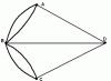
For geometric construction For images in mirrors, it is necessary to use “convenient” rays.

One of the rays is “focal”, a ray parallel to the optical axis is reflected so that the reflected ray (or its dotted extension) passes through the focus. The other ray is “polar”, it is reflected at the vertex (pole). It is clear that the angles of incidence and reflection are equal, so such a ray can be constructed by symmetrically mapping the incident ray downward. The figures show the construction of images in concave (A’ – real, B’ – imaginary) and convex mirrors. In addition to these rays, you can use another ray, think about which one.
I note that obtaining a point image in a mirror is possible only when using paraxial (paraaxial) beams of rays. Wide beams of rays lead to the same aberrations as in lenses.