A special case of central projection with the center of projections located at infinity (at an improper point O). Carried out by a bunch of rays of a given direction S(Fig. 2).
Parallel projection device:
projection plane;
S- direction of projection;
[O A][ O B] S
A = [O.A.] - parallel projection of point A onto the plane;
l = (A.A. BB) - parallel projection of a line onto the plane .
There is no reversibility. One central projection point does not allow us to judge the position of the point in space. A = D
Geometric figures are projected onto the projection plane, in general case, with distortion. The nature of the distortion depends on the projection apparatus and the position of the projected figure relative to the projection plane.
In particular, with parallel projection, the metric characteristics of geometric figures are violated (linear and angular values are distorted). Some properties of a figure are preserved in its projection.
The properties of a figure that are preserved in the projection are called independent or invariant. These invariant properties are often called invariants for short.
Invariants parallel projection
The projection of a point is a point (Fig. 1; Fig. 2)

The projection of a straight line is a straight line (Fig. 1; Fig. 2)

3 . The projection of a point belonging to a line belongs to the projection.
this straight line (Fig. 1; Fig. 2)

The projection of the point of intersection of lines is determined by the intersection of the projections of these lines (Fig. 3)
Projections of mutually parallel lines are mutually parallel (Fig. 4)

The ratio of the lengths of segments of mutually parallel straight lines is equal to the ratio of the lengths of their projections (Fig. 4)

IMPACT: if a line segment is divided by a point in any ratio, then the projection of the segment is divided by the projection of this point in the same ratio (Fig. 5)

7 . A flat figure parallel to the projection plane is projected onto this plane into a congruent figure (Fig. 6)


Rice. 3 Fig. 4


Rice. 5 Fig. 6
Rectangular (orthogonal) projection
A special case of parallel projection, in which the projection direction is perpendicular to the projection plane (Fig. 7)

In what follows, orthogonal projection is used unconditionally.
Orthographic projection retains all the properties of parallel projection. In addition, for orthogonal projection the projection theorem holds right angle(see topic No. 6) and apply a method for determining the distance between points (i.e., the length of a segment, see topic No. 3), called the right triangle method.

Rice. 7
MORE DETAILS...
The position of an object in space is determined by its four points that do not lie in the same plane. Image spatial object in the drawing comes down to constructing projections of many points of this object on a plane R(called the projection plane) using straight lines (projection rays) passing through the points of the object and directed towards the center of projection S.
However, to construct a projection of an object, it is not necessary to construct all its points. It is enough to find only the projections of characteristic points (vertices, edges, etc.), which are then connected by the corresponding line.
The projecting rays together form projection surface. So, when projecting a straight line AB, the projecting surface is the plane AB ba(rice.).
Intersection line ab projection plane with plane R is a projection of a straight line AB, which is composed of projections of its individual points.
Projection is like a shadow cast from an object illuminated by a lamp or the sun.
When projecting a curved line in the first case, the projecting rays form conical surface with vertex at point S, it turns out To onic (perspective) image of the curve (Fig. 2). In the second case, the cone of projecting rays turns into a cylinder and the conical image becomes cylindrical (parallel) (Fig. 2). The projection of a curved line is considered as the line of intersection of the projecting surface with the plane R.
In perspective, an object is depicted as it appears to the eye of the observer. The lens of the eye is the center of projection. Each of us is familiar with the following phenomenon: if you look along the canvas railway, it seems to us that the rails seem to be approaching each other and converging on the horizon to one point (the center), and the supports located along the tracks decrease as they move away.
Parallel projection -special case prospects. The essence of parallel projection is as follows: if we conditionally remove the center of projection to infinity, then the projecting rays can be considered parallel.
So, to construct a parallel projection of a triangle ABC(Fig.), you need to set: R- projection plane (not parallel and not coinciding with the direction of the projecting rays); S- direction of the projecting rays (projection direction).
Next, through characteristic points objects are carried out by projecting rays Ahh,Bb And Ss parallel to the projection direction, and then find the points a,b and from their intersection with the plane R. These points are the required parallel projections of the points A,IN And WITH given triangle.
Projection abc- line of intersection of the projecting prismatic surface with the plane R. The shape and dimensions of a parallel projection of an object for a given projection direction depend only on the choice of direction of the projection plane and do not depend on its distance from the object. Triangle located in a plane R 1, parallel to the projection plane, is projected equal to the given one. In this case ab=AB,bc=B.C.,ac=A.C..
Depending on the angle of inclination of the projecting beam to the projection plane, parallel projection is divided into two types: rectangular and oblique.
RECTANGULAR(or orthogonal) projection is called when the projection direction is chosen perpendicular to the projection plane. In another case it is called OBLIQUE.
With rectangular projection (Fig. 7), the distortion coefficient cannot exceed unity.
In oblique projections (Fig. 5), the distortion coefficient ( TO=ab/AB) of this segment AB can take on any numerical values depending on the inclination of the segment and the projecting rays to the projection plane. In particular, if the direction of a segment coincides with the direction of projection, then the projection of this segment will be a point, and the distortion coefficient will be zero.
In parallel projection, the basic properties prospects, namely:
1) the projection of a point is a point;
2) the projection of a line in the general case will be straight;
3) each point belonging to a line corresponds to a projection of this point on the projection of this line.
In addition, parallel projection has a number of other (only inherent) properties:
4) if a point lies on a line segment, then the projection of this point divides the projection of the segment in the same ratio as
a point divides a segment, i.e. A.C./C.B.=ac/cb(Fig. 5);
5) the projection of intersecting segments will also be intersecting segments, and the point of their intersection will be the projection of the point of intersection of these segments (Fig. 3);
6) projections parallel segments parallel, in the same direction, and their ratio is equal to the ratio of the lengths of the segments, i.e. abCD And AB/CD=ab/CD(Fig. 4);
with rectangular projection, a right angle is projected by a right angle only if one of its sides is parallel to the projection plane and the second is not a projecting ray (right angle projection theorem).
Parallel projection
The special case of central projection, when the center of projection S is removed to infinity from the projection plane P¢, has become widespread in practice. The projecting rays are practically parallel to each other, therefore this method got the name parallel projection , and the images (projections) of the figure obtained with its help on the plane are called parallel projections .
|
Let's take some figure in space, for example line AB (Figure 1-2). Let's project it onto the projection plane P¢. We indicate the direction of projection with an arrow S. To project point A onto the plane P¢, you need to draw a straight line through this point parallel to the direction S until it intersects with the projection plane P¢. The resulting point A¢ is called parallel projection of point A. Similarly, we find the projections of other points on line AB.
The set of all projecting rays defines (represents) in space cylindrical surface, therefore this method of projection is called cylindrical.
2.3 Basic properties of parallel projection
1) The projection of a point is a point. АÞА¢ (Figure 1-3a).
 |
2) The projection of a line is a straight line (straightness property).
Indeed, with parallel projection, all projecting rays will lie in the same plane E. This plane intersects the projection plane in a straight line l¢ (Figure 1-3b).
3) If a point in space belongs to a line (lies on it), then the projection of this point belongs to the projection of the line ( membership property), (Figure 1-3b, point M).
4) Projections of mutually parallel lines are also mutually parallel, because (Figure 1-3b, c), ( l )ll( m )Þ ( l ¢) II ( m ").
5) If a line segment is divided by a point in some ratio, then the projection of the segment is divided by the projection of this point in the same ratio.
Let’s prove this: introduce CE//A’C" and DB//C"B" ,
Then ![]() . From the similarity of triangles it follows that
. From the similarity of triangles it follows that
½AC½/½CB½=½CE½/½DB½=½A¢C¢½/½C¢B¢½.
6) Parallel transfer projection plane or figure (without rotation) does not change the appearance and size of the figure projection (Figure 1-4).

2.4 Rectangular projection
 A special case of parallel projection, in which the projection direction S is perpendicular to the projection plane P¢, further simplifies the construction of the drawing and is most often used in design practice. This method is called rectangular projection
or (which is also) orthogonal projection.
A special case of parallel projection, in which the projection direction S is perpendicular to the projection plane P¢, further simplifies the construction of the drawing and is most often used in design practice. This method is called rectangular projection
or (which is also) orthogonal projection.
 The method of orthogonal projections was first introduced by the French geometer Gaspard Monge, which is why it is sometimes called Monge's method. This method is the main one when drawing up technical drawings, since it allows you to most fully judge the size of the depicted objects. In this case, it is not difficult to establish the relationship between the length of a certain segment AB in space and the length of its projection A¢B¢ (Figure 1-5).
The considered methods of projection allow us to unambiguously solve the direct problem - to build it from a given original projection drawing. However only one a parallel projection without any additions is not sufficient to provide a complete picture of what this object is like in real life. From such an image (Figure 1-6) it is impossible to determine not only the shape and size of an object, but also its position in space, i.e. parallel projection does not have the property of reversibility. To obtain reversible drawings, the projection drawing is supplemented with the necessary data. Supplementation methods vary. We are aware descriptive geometry We will consider two types of reversible drawings:
1. complex drawings in orthogonal projections;
2. axonometric drawings.
In geometry problems, success depends not only on knowledge of the theory, but on a high-quality drawing.
With flat drawings everything is more or less clear. But in stereometry the situation is more complicated. After all, it is necessary to depict three-dimensional body on flat drawing, and in such a way that both you and the person looking at your drawing would see the same volumetric body.
How to do this?
Of course, any image of a volumetric body on a plane will be conditional. However, there is a certain set of rules. There is a generally accepted way of constructing drawings - parallel projection.
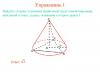
Let's take a volumetric body.
Let's choose projection plane.
Through each point of the volumetric body we draw straight lines parallel to each other and intersecting the projection plane at any angle. Each of these lines intersects the projection plane at some point. And all together these points form projection of a volumetric body onto a plane, that is, its flat image.
How to construct projections of volumetric bodies?
Imagine that you have a frame of a volumetric body - a prism, pyramid or cylinder. By illuminating it with a parallel beam of light, we get an image - a shadow on the wall or on the screen. Note that different angles produce different images, but some patterns are still present:
The projection of a segment will be a segment.

Of course, if the segment is perpendicular to the projection plane, it will be displayed at one point.
In the general case, the projection of a circle will be an ellipse.
The projection of a rectangle is a parallelogram.

This is what the projection of a cube onto a plane looks like:

Here the front and back faces are parallel to the projection plane
You can do it differently:

Whatever angle we choose, projections of parallel segments in the drawing will also be parallel lines . This is one of the principles of parallel projection.
We draw projections of the pyramid,

cylinder:

Let us repeat once again the basic principle of parallel projection. We select a projection plane and draw straight lines parallel to each other through each point of the volumetric body. These lines intersect the projection plane at any angle. If this angle is 90° - we're talking about O rectangular projection. Using rectangular projection, drawings of volumetric parts in technology are constructed. In this case we are talking about top view, front view and side view.
Issues covered:
- 1. The concept of projection
- 4. Monge method
- 5. Axonometric projection
The concept of projection. Images of objects in drawings are obtained by projection . Projection is the process of constructing an image of an object on a plane using projecting rays. The result of this process is an image called projection.
The word “projection” translated from Latin means throwing forward, into the distance. Projection can be observed by looking at the shadow cast by an object on the surface of a wall when the object is illuminated by a light source. computer graphics projection sketching
Projection refers to the process that results in images (projections on a plane), i.e. when rays are drawn through the characteristic points of a figure until they intersect with the plane, and the resulting points from the intersection of the rays with the plane are connected by straight or curved lines accordingly.
Central (conical) projection. There will be a plane P1 in space, let's call it the projection plane or the picture plane. Let us take any point S that does not belong to the projection plane P1. Let's call it the center of projection (Fig. 19).
To project the figure ABC, called the original, it is necessary to draw straight lines from point S through points A, B, C, called projecting rays, until they intersect with the plane P1 at points A1, B1, C1. By connecting them sequentially with straight lines, we get the figure A1B1C1. This will be the central projection A1B1C1 of this figure ABC onto the projection plane P1.
Fig. 19.
Parallel (cylindrical) projection. With parallel projection, as in the case of central projection, the projection plane P1 is taken, and instead of the center of projections S, the projection direction is specified.
We set the direction of projection S not parallel to plane P1, considering that point S - the center of projection - is removed to infinity. The original projection is the same figure ABC, located in space. To project the figure ABC, we draw projecting rays through points A, B, C parallel to the projection direction S until they intersect with the projection plane P1 at points A1, B1, C1. We connect points A1, B1, C1 with straight lines, we get figures A1B1C1; this will be a parallel projection of the figure ABC onto the plane P1. This is the process of parallel projection (Fig. 20).

Fig.20.
If the original is a straight line, then all the projecting rays of the points of this straight line will be located in one plane, called the projecting plane.
Plane P, passing through the projection lines BB1 and CC1, intersects the projection plane P1 along a straight line. This line can be considered as a projection of the line, given by points B and C. Depending on the direction of projection S to the projection plane, parallel projection is divided into rectangular (orthogonal) and oblique projection (Fig. 21).

Fig.21 Rectangular and oblique projection
Rectangular projection , when the direction of projection S with the projection plane makes a right angle (Fig. 21a).
Oblique projection , when the projection direction makes an angle less than 90? with the projection plane (Fig. 21b).
Monge method. Information and methods of construction, determined by the need for flat images of spatial forms, have been gradually accumulated since ancient times. Over a long period flat images were performed primarily as visual images. With the development of technology, the question of using a method that ensures the accuracy and measurability of images, that is, the ability to accurately determine the location of each point of the image relative to other points or planes and by simple techniques Determine the sizes of line segments and shapes. Gradually accumulated separate rules and the techniques for constructing such images were systematized and developed in the work of the French scientist Gaspard Monge, published in 1799.
Rectangular projection is a special case of parallel projection. The method of orthogonal projections is called Monge method . This method is the most common when preparing technical drawings. It does not provide clarity of the image, but it is simple and convenient when making a drawing and provides high accuracy. Monge method is a rectangular parallel projection onto two mutually perpendicular planes projections. Such a complex of two interconnected orthogonal projections reveals the position of the projected object in space. The method outlined by Monge ensures expressiveness, accuracy and measurability of images of objects on a plane; it was and remains the main method for drawing up technical drawings (Figure 22).
The word rectangular is often replaced by the word orthogonal, formed from the words ancient Greek language, denoting “straight line” and “angle”. In the following presentation, the term orthogonal projections will be used to denote the system rectangular projections on mutually perpendicular planes. Figure 22 shows two mutually perpendicular planes. Let us take them as projection planes. One of them, designated by the letter P1, is located horizontally; the other, designated by the letter P2, is vertical. This plane is called frontal plane projections, plane P1 is called horizontal plane projections . The projection planes P1 and P2 form the system P1, P2.
The line of intersection of projection planes is called projection axis . The projection axis divides each of the planes P1 and P2 into half-planes. For this axis we will use the notation x or the notation in the form of the fraction P2 / P1.

Fig.22.
Axonometric projection. If an object with axes assigned to it rectangular coordinates position in front of the projection plane and project parallel rays onto one plane, which in this case is called the picture plane, then we get axonometric projection.
In Fig. Figure 23 shows the cube, the axes of rectangular coordinates x0, y0, z0 assigned to it, the projection plane P and axonometric image Cuba.


Fig.23. Education axonometric projections: a and b - frontal dimetric; c and d - isometric
Axonometry - a Greek word, translated means measurement along axes. When constructing axonometric projections, dimensions are laid along the x, y, z axes.
Axonometric projections are quite visual, so in a number of cases they are used to explain rectangular projections of complex machines and mechanisms and their individual parts. With axonometric projection, a figure is associated with a spatial system of coordinate axes, then this figure with the coordinate axes is projected onto one plane. This plane is called plane of axonometric projections.
Axonometric projections obtained by rectangular projection of a figure with coordinate axes, are called rectangular, and those obtained by oblique projection are called oblique.
Projection plane called the plane on which the projection of an object is obtained.