PROJECTION DRAWING
Descriptive geometry studies methods for constructing images of spatial figures on a plane and solutions spatial problems on the drawing.
Projection drawing is considering practical questions constructing drawings and solving problems using the methods discussed in descriptive geometry, first on the drawings geometric bodies, and then on drawings of models and technical details.
METHODS OF OBTAINING GRAPHIC IMAGES
The shape of any object can be considered as a combination of individual simple geometric bodies. And to depict geometric bodies you need to be able to depict them individual elements: vertices (points), edges (straight lines), faces (planes).
The basis for constructing images is the method of projection. To obtain an image of an object means to project it onto the drawing plane, i.e. project its individual elements. Since the simplest element of any figure is a point, the study of projection begins with the projection of a point.
To obtain an image of point A on plane P (Fig. 4.1), a projecting beam Aa is passed through point A. The point of intersection of the projecting ray with the plane P will be the image of point A on the plane P (point a), i.e., its projection onto the plane P.
This process of obtaining an image (projection) is called projection. The P plane is the projection plane. On it an image (projection) of an object is obtained, in in this case points.
The principle of projection can be easily understood by the example of obtaining the shadow of an object on a wall or a sheet of paper. In Fig. 4.1 shows the shadow of a pencil illuminated by a lamp, and in Fig. 4.2 - shadow of a pencil, illuminated sunlight. If you imagine light rays straight lines, that is, projecting rays, and the shadow is a projection (image) of an object on a plane, then it is easy to imagine the projection mechanism.

Depending on the relative position of the projecting rays, projection is divided into central and parallel.
CENTRAL AND PARALLEL PROJECTION
Center projection - obtaining projections using projection rays passing through point S, which is called the projection center (Fig. 4.3). If we consider the lamp to be a point source of illumination, then the projecting rays come out from one point, therefore, on the plane P a central projection of a pencil is obtained (Fig. 4.1).
An example of center projection is the projection of movie frames or slides onto a screen, where the frame is the object of projection, the image on the screen is the projection of the frame, and the focus of the lens is the center of the projection.

The images produced by central projection are similar to the images on the retina of our eyes. They are visual and understandable to us, as they show us the objects of the surrounding reality as we are accustomed to seeing them. But the distortion of the sizes of objects and the complexity of constructing images during central projection do not allow its use for making drawings.
Central projections are widely used only where clarity in images is needed, for example, in architectural and construction drawings when depicting perspectives of buildings, streets, squares, etc.
Parallel projection . If the center of projection, point S, is removed to infinity, then the projecting rays will become parallel to each other. In Fig. Figure 4.4 shows the receipt of parallel projections of points A and B on the plane P.
Depending on the direction of the projecting rays in relation to the projection plane, parallel projections are divided into oblique and rectangular.
At oblique projection the angle of inclination of the projecting rays to the projection plane is not equal to 90° (Fig. 4.5).
With rectangular projection, the projecting rays are perpendicular to the projection plane (Fig. 4.6).
The projection methods discussed above do not establish a one-to-one correspondence between the object (point A) and its image (projection). For a given direction of the projecting rays on the projection plane, only one projection of the point is always obtained, but it is impossible to judge the position of the point in space from one of its projections, since on the same projecting ray Aa (Fig. 4.7) the point can occupy various provisions, being above or below a given point A, and what position of the point in space corresponds to the image (projection) a, it is impossible to determine.


Rice. 4.4. Rice. 4.5. Rice. 4.6.

In order to determine its position in space from the image of a point, it is necessary to have at least two projections of this point. It should be known relative position projection planes and projection direction. Then, having two images of point A, it will be possible to imagine how the point is located in space.
The simplest and most convenient is to project onto mutually perpendicular planes projections using projection rays perpendicular to the projection planes.
This projection is called orthogonal projection, and the resulting images are called orthogonal projections.
Central projection. Properties of central projection. Examples of central projection of a point, a straight segment of a triangle
Answer: CENTRAL PROJECTION
The main types of projection are central and parallel. Central projection is the general case of projecting geometric images from some center onto a plane.
Let a plane P1 and a curved line k with points A, B, C be given (Fig. 1.1).
Fig.1.1
Let us take some point S that does not lie in the plane P1. Through point S and points A, B, C of curve k we draw straight lines until they intersect with plane P1 at points A1, B1, C1. Having thus drawn straight lines through S and each point of the curve k, we obtain an image k1 of the curve k in the P1 plane.
In accordance with the described construction, we introduce the following concepts:
S - center of projections; P1 - projection plane; curve k with points A, B, C - projection object; SA, SB, SC - projecting rays; A1,B1,C1 - central projections of points A, B, C; k1 - central projection of curve k. Considering each spatial figure as a collection of points, we can say that the projection of a figure is a set of projections of its points.
Center projection properties:
1. Any point (except S) is projected onto the projection plane into a single point (Fig. 1).
2. Each point (A, B, C, D,...) belonging to any line (curve or straight) corresponds to the projection (A1, B1, C1, D1, ...) of this point on the projection of this line (Fig. 1).
3. Curve in general case is projected into a curve, and a straight line into a straight line. If the straight line coincides with the projecting ray, for example DE (Fig. 1), then it is projected to the point D1 º E1. The plane passing through the center of the projections is projected into a straight line and is called projecting. A curve, all points of which belong to the projecting plane, is projected into a straight line.
4. The point of intersection of the lines is projected to the point of intersection of the projections of these lines (Fig. 1).
Central projection is highly visual and is used in construction drawing, architecture, painting, etc. The disadvantage of central projection is the difficulty of constructing an image of an object and determining its true dimensions. Therefore, it has limited use in technical drawing.
Parallel projection properties of parallel projection. Examples of parallel projection of a point on a straight line segment of a triangle
1.3.3 Parallel projection
Parallel projection can be thought of as special case central projection.
If the center of projections with the central projection apparatus is moved to infinity, then the projecting rays can be considered parallel. Hence, the parallel projection apparatus consists of a projection plane P and a direction P. With central projection, the projecting rays come out from one point, and with parallel projection they are parallel to each other.
Depending on the direction of the projecting rays parallel projection can be oblique, when the projecting rays are inclined to the projection plane, and rectangular (orthogonal), when the projecting rays are perpendicular to the projection plane.
Let's look at an example of oblique parallel projection.
Let us construct a parallel projection A1B1 of the segment AB onto the plane P1, for a given projection direction P not P1. To do this, it is necessary to draw projecting lines through points A and B, parallel to the direction of projection P. When the projecting lines intersect with plane P1, we obtain parallel projections A1 and B1 of points A and B. By connecting parallel projections A1 and B1, we obtain a parallel projection A1B1 of segment AB.
Similarly, it is possible to construct a parallel projection A1B1C1D1 of the quadrilateral ABCD onto the plane P1, for a given projection direction P not P1.
Click on the picture to view...
To do this, it is necessary to draw projecting lines through points A, B, C, D, parallel to the projection direction P. When the projecting lines intersect with plane P1, parallel projections A1, B1, C1, D1 of points A, B, C, D will be obtained. By connecting the parallel projections A1, B1, C1, D1 we get a parallel projection A1B1C1D1 of the quadrilateral ABCD.
Properties of projections during parallel projection:
The first six properties of central projection also apply to parallel projection. Let's list a few more properties inherent in parallel projection:
Projections of parallel lines are parallel.
Click on the picture to view...
The figure shows that straight lines AA1, BB1, CC1 and DD1 form two parallel planes a and b. These two planes intersect with P1. Consequently, the lines of intersection of their A1B1 and C1D1 will be parallel.
If a point divides the length of a segment in the ratio m:n, then the projection of this point divides the length of the projection of the segment in the same ratio.
Click on the picture to view...
Let the point C belong to the segment AB, and |AC| : |SV| = 2: 1. Let’s construct a parallel projection A1B1 of segment AB. Point C1 A1B1. Let's carry out AC" || A1C1 and CB" || C1B1, we get two similar triangles ACC" and CBB". From their similarity follows the proportionality of the sides: |AC| : |SV| = |AC"| : |CB"|, but |CB"| = |С1В1|, and |AC"| = |A1C1|, hence |AC| : |SV| = |A1C1| : |C1B1|.
A flat figure parallel to the projection plane is projected without distortion.
Click on the picture to view...
Let's take triangle ABC and project it onto two parallel planes of projections P1" and P1. Since the lengths of the segments are equal to |A1 A1"| = |B1 B1"| = |C1 C1"| and the segments are parallel, then the quadrilaterals A1 A1" B1 B1", B1 B1" C1C1", C1 C1" A1A1" are parallelograms. Consequently, their opposite sides are equal in length |A1 B1| = |A1" B1"|, |B1 C1| = |B1" C1"|, |A1 C1| = |A1" C1"|, which means the triangles are equal.
Similarly, the same can be proven for any other flat figure. Parallel projection, unlike central projection, is less visual, but provides ease of construction and greater connection with the original.
Orthogonal projection properties of orthogonal projection Monge diagrams point in a system of two planes point in a system of three planes coordinates of a point
As mentioned above, orthogonal projection is a special case of parallel projection. With orthogonal projection, the projecting rays are perpendicular to the projection plane.
The apparatus of such projection consists of one projection plane.
Click on the picture to view...
To obtain an orthogonal projection of point A, a projection ray must be drawn through it perpendicular to P1. Point A1 is called an orthogonal or rectangular projection of point A.
Click on the picture to view...
To obtain the orthogonal projection A1B1 of the segment AB onto the plane P1, it is necessary to draw projecting straight lines, P1, through points A and B. When the projecting lines intersect with the plane P1, we obtain orthogonal projections A1 and B1 of points A and B. By connecting the orthogonal projections A1 and B1, we obtain the orthogonal projection A1B1 of the segment AB.
All properties of parallel projection are also valid for orthogonal projection. However, orthogonal projections have some other properties.
Properties orthogonal projection:
The length of a segment is equal to the length of its projection divided by the cosine of the angle of inclination of the segment to the projection plane.
Click on the picture to view...
Let's take straight line AB and construct its orthogonal projection A1B1 onto plane P1. If you draw a straight line AC || A1B1, then from triangle ABC it follows that |AC| : |AB| = cos a or |AB| = |A1B1| : cos a, because |A1B1| = |AC|.
In addition, for orthogonal projection the projection theorem will be valid right angle: Theorem:
If at least one side of a right angle is parallel to the projection plane, and the other is not perpendicular to it, then the angle is projected onto this plane in full size.
Click on the picture to view... Proof:
Given a right angle ABC, which by condition has a straight line BC AB and BC || projection plane P1. According to the construction, there is a straight line BC to the projecting beam BB1. Consequently, straight line BC is to plane b (ABxBB1), since it is to two intersecting lines lying in this plane. According to the condition, straight line В1С1 || BC, therefore also to the plane b, i.e., to the straight line A1B1 of this plane. Therefore, the angle between straight lines A1B1 and B1C1 is equal to 90°, which is what needed to be proven.
Orthogonal projection provides simplicity of geometric constructions when determining orthogonal projections of points, as well as the ability to preserve the shape and dimensions of the projected figure on the projections. These advantages have ensured that orthogonal projection is widely used in technical drawing.
The projection methods considered make it possible to solve the direct problem of descriptive geometry, that is, to construct a flat drawing from the original. The projections onto one plane obtained in this way give an incomplete idea of the object, its shape and position in space, i.e. such a drawing does not have the property of reversibility.
To obtain a reversible drawing, i.e. a drawing that gives a complete picture of the shape, size and position of the original in space; a one-picture drawing is supplemented. Depending on the supplement there are various types drawings.
Monge diagram or orthogonal projections.
The essence of the orthogonal (rectangular) projection method is that the original is orthogonally projected onto 2 or 3 mutually orthogonal projection planes, and then combine them with the drawing plane.
Axonometric drawing.
The essence of the axonometric drawing is that first the original is rigidly connected to the Cartesian coordinate system OXYZ, and it is orthogonally projected onto one of the projection planes OXY, or OXZ. Then, by parallel projection, a parallel projection of the resulting structure is found: coordinate axes OX, OY, OZ, secondary projection and original.
Perspective drawing.
When constructing a perspective drawing, first one constructs one orthogonal projection, and then on the picture plane the central projection of the previously constructed orthographic projection and the original itself is found.
Projections from numerical marks etc.
To obtain projections with numerical marks, project the original orthogonally onto a plane zero level and indicate the distance from the original points to this plane.
Let's look at the study in more detail rectangular projections and axonometric drawing.
Orthogonal projections of a line segment general position straight lines and their projections. Projecting straight lines and their projections are examples of constructing horizontal and frontal lines.
A straight line of particular position (or a straight line of a level) is a straight line parallel to at least one of the projection planes.
1. A straight line parallel to the horizontal plane of projections is called the horizontal - h. On the horizontal projection plane, the horizontal is projected in natural size.
2. The straight line parallel to the frontal plane of projections is called frontal - v. On the frontal plane of projections, the frontal is projected in natural size.
3. A straight line parallel to the profile plane of projections is called a profile straight line - w. The profile line is projected in full size onto the profile projection plane.
A line is called projecting if it is perpendicular to one of the projection planes. One of the projections of such a line is a point. This projection is called principal or degenerate. All points of the projecting line are competing.
1. Horizontally projecting line - a line of the horizontal projection plane. The horizontal projection of such a line is a point, and the frontal and profile projections || z axis
2. Frontally projecting straight line - straight line of the frontal plane of projections. The frontal projection of such a line is a point, and the horizontal and profile projections || y axis.
3. Profile projecting straight line - straight line of the profile projection plane. The profile projection of such a straight line is a point, and the horizontal and frontal projection|| x-axis.
Traces of a straight line examples of determining traces of a straight line in general position of straight lines of a level
Traces of a straight line
The trace of a straight line is the point of its intersection with a certain plane or surface (Fig. 20).
The horizontal trace of a line is a certain point H at which the line meets horizontal plane, and frontal - point V, at which this straight line meets the frontal plane (Fig. 20).
Figure 21a shows the horizontal trace of a straight line, and its frontal trace is shown in Figure 21b.
Sometimes the profile trace of a straight line is also considered, W is the point of intersection of the straight line with the profile plane.
The horizontal trace is in the horizontal plane, i.e. its horizontal projection h coincides with this trace, and the frontal h́ lies on the x axis. The frontal trace lies in the frontal plane, therefore its frontal projection ν́ coincides with it, and the horizontal projection v lies on the x axis.
So, H = h, and V = ν́. Consequently, the letters h and ν́ can be used to denote traces of a straight line.
The relative position of a point and a line; the relative position of a point and a plane; an example of determining the missing projection of a point lying in a given plane of a triangle
1.8.3. Mutual position of points and line
A point can either lie on a line or be outside it. If
the point is on a straight line, then in accordance with the property of belonging
location (see 3.3), its projections must lie on the same
straight projections.
If the point is outside the line, then at least one of the projections
tions of the point will not lie on the projection of the line of the same name (Fig.
no. 29, points B, C, D).
Figure 29 shows that point B is located
l extends over the line l, because it is located
higher than horizontally competing with
it and a point lying on a straight line is marked
cross. Here you can see that point C
is located behind straight line l, since it is on-
frontally competing with it point from-
l marked with a cross. About point D we can say
say that it is closer and lower than the straight line
my l, because it is closer and lower than the point lying
Figure 29
on a straight line (marked with a cross).
To determine the position of a point relative to the profile
Thus:
definition mutual position points and straight lines
goes to determining the relative position of two points.
§ 49. The relative position of a point, a line and a plane
A straight line may or may not belong to a plane. It belongs to a plane if at least two of its points lie on the plane. In Fig. 93 shows the Sum (axb) plane. The straight line l belongs to the plane Sum, since its points 1 and 2 belong to this plane.
If a line does not belong to the plane, it can be parallel to it or intersect it.
A straight line is parallel to a plane if it is parallel to another straight line


mine, lying in this plane. In Fig. 93 straight m || Sum, since it is parallel to the line l belonging to this plane.
A straight line can intersect a plane at different angles and, in particular, be perpendicular to it. The construction of lines of intersection of a straight line and a plane is given in §61.
A point in relation to the plane can be located in the following way: belong to it or not belong to it. A point belongs to a plane if it is located on a straight line located in this plane. In Fig. 94 shows a complex drawing of the plane Sum, defined by two parallel straight lines l and p. The line m is located in the plane. Point A lies in the Sum plane, since it lies on the line m. Point B does not belong to the plane, since its second projection does not lie on the corresponding projections of the line.
The relative position of two straight lines, examples of determining the distance between parallel straight lines, crossing straight lines by replacing projection planes
The theorem on the projection of a right angle; drawing a perpendicular to the horizontal front; an example of constructing a perpendicular to a plane from a given point
The solution of many metric problems requires the use of perpendicular lines and planes and is based on the properties of rectangular projection of a right angle.
A right angle is projected without distortion if both sides are parallel to the projection plane. If the sides of the angle are not parallel to the projection plane, then the angle is projected with distortion onto this projection plane.
We considered the right angle projection theorem when studying the properties of orthogonal projection. Let us recall this theorem.
If at least one side of a right angle is parallel to the projection plane, and the other is not perpendicular to it, then the angle is projected onto this plane in full size. Corollary: if the rectangular projection of an angle, one side of which is parallel to the plane of projections, is a right angle, then the projected angle is also a right angle.
The properties of right angle projections are important when solving metric problems in the drawing, such as constructing mutually perpendicular straight lines and planes for determining the distance between geometric figures, etc. 
Methods for specifying a plane in a drawing; relative position of planes; sign of parallelism of two planes; example of constructing a plane parallel to a given plane through a given point
Various ways to define a plane in a drawing
The position of the plane in space is determined:
a) three points that do not lie on the same straight line, b) a straight line and a point taken outside the straight line, c) two intersecting straight lines, d) two parallel straight lines.
In accordance with this, the plane can be specified in the drawing:
a) projections of three points that do not lie on the same line (Fig. 97), b) projections of a line and a point taken outside the line (Fig. 98), c) projections of two intersecting lines (Fig. 99), d) projections of two parallel straight (Fig. 100).
Each of those shown in Fig. 97-100 plane jobs can be converted to another of them. For example, by drawing a straight line through points A and B (Fig. 97), we obtain the plane shown in Fig. 98; From this we can move on to Fig. 100 if through point C we draw a line parallel to line AB.
The plane can be specified in the drawing and by projections of any flat figure (triangle, square, circle, etc.). Let some pl. a is determined by points A, B and C (Fig. 101). Drawing straight lines through the projections of these points of the same name, we obtain the projections of triangle ABC. Point D, taken on line AB, thereby belongs to the square. A; drawing a straight line through point D and through another point that obviously belongs to the square. and (for example, through point C), we get another straight line in the square. ABOUT!,
Similarly, straight lines can be constructed, and therefore points belonging to a plane defined by any of the above methods.
Later we will see that a plane perpendicular to the projection plane can be specified by a straight line along which these planes intersect each other.

Projections of planes of a particular position (level planes, projecting planes) mutual arrangement of planes sign of perpendicularity of two planes example of constructing plane b through a given point perpendicular to a given plane a
2.5.2 Orthogonal drawing of a partial plane
The plane of particular position is the plane passing through the projecting lines, i.e. perpendicular to one or simultaneously to two main projection planes. If a plane is perpendicular to only one projection plane, then it is called a projection plane. There are three types of projection planes: 1. Horizontal projection plane - perpendicular to P1. And therefore it is projected onto it as a straight line.
2. Frontal projection plane - perpendicular to P2. And therefore it is projected onto it as a straight line.
3. Profile-projecting plane - perpendicular to P3. And therefore it is projected onto it as a straight line. In a normal orthogonal drawing, when plane P3 is not used, the profile-projecting plane looks like a general plane.
If a plane is perpendicular to two projection planes, then it is called a level plane. Consequently, the level plane is always parallel to one of the projection planes. There are three types of level planes: 1. Horizontal level plane - || P1.
2. Frontal plane of the level - || P2.
3. Profile plane of the level - || P3.


Adele - Someone Like You
That you"re settled down
That your dreams came true.
Guess she gave you things
I didn't give to you
Why are you so shy?
Ain't like you to hold back
Or hide from the light
That for me it isn't over
I"ll find someone like you
Don"t forget me I beg
I remember you said
"Sometimes it lasts in love
But sometimes it hurts instead."
Sometimes it lasts in love
But sometimes it hurts instead,
It was the time of our lives
We were born and raised
In a summer haze
Bound by the surprise
Of our glory days
I hate to turn up out of the blue uninvited
But I couldn't stay away, I couldn't fight it.
I had hoped you"d see my face and that you"d be reminded
That for me it isn't over, yeah.
I"ll find someone like you
I wish nothing but the best for you too
Don"t forget me I beg
I remember you said
"Sometimes it lasts in love
Nothing compares
No worries or cares
Regrets and mistakes
And memories made.
Who would have known
Would this taste?
I"ll find someone like you
I wish nothing but the best for you too
Don"t forget me I beg
I remember you said,
"Sometimes it lasts in love
But sometimes it hurts instead"
I"ll find someone like you
I wish nothing but the best for you, too
Don"t forget me I beg
I remember you said
"Sometimes it lasts in love
But sometimes it hurts instead"
Sometimes it lasts in love
But sometimes it hurts instead
Lyrics to Adele - Someone Like You
The basis for the rules for constructing images, considered in descriptive geometry and used in technical drawing, is the projection method. The study begins with the construction of projections of a point, since when constructing an image of any spatial shape, a number of points belonging to this shape are considered.
The following notations are used in the book:
Central projections and their basic properties
At central projection– constructing central projections – specify the projection plane and the projection center – a point not lying in the projection plane. In Fig. 1.1 plane I – projection plane, point S– projection center.
For projection arbitrary point a straight line is drawn through it and the center of projection. The point of intersection of this line with the projection plane is the central projection of a given point on the selected projection plane.
In Fig. 1.1 central projection of a point A is the point of intersection of the line S.A. with plane To. The central projections of the points were also constructed B, C, D on the plane.
Lines passing through the center of projection and the projected points are called projecting lines.
The central projections of two different points 5i in space, which are located on the same projecting line, coincide. The entire set of points in space belonging to the same


noic projection line, has, with one projection center, one central projection on a given projection plane.
Therefore, when given planes projections and projection center, one point in space has one central projection. But one central projection of a point does not allow one to unambiguously determine the position of the point in space, i.e., there is no reversibility of the drawing.
To ensure the reversibility of the drawing, i.e. unambiguous definition position of a point in space according to its projection, we need additional conditions, for example, you can specify a second projection center. Central projection can be used to construct a projection of any line or surface as a set of projections of all its points. In this case, the projecting straight lines in their totality, drawn through all points of the curved line, form a projecting conical surface (Fig. 1.2) or may end up in the same plane, as, for example, in the case shown in Fig. 1.4.
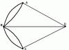
The projection of a curved line is the line of intersection of the projecting conical surface with the projection plane. So, in Fig. 1.2 projecting conical surfaceβ intersects the projection plane i along the curve А°В°, which is a projection of the line AB. However, the projection of a line does not determine the projected line, since there can be an infinite number of lines on the projecting surface projecting into the same line on the projection plane (Fig. 1.3).
When projecting a straight line that does not pass through the center of projection, the projection surface is a plane. So, in Fig. 1.4 projection plane γ formed by projection lines S.C. And SD passing through points C and D straight, ne-

cuts the projection plane l in a straight line C °D°, which is the projection of the straight line CD. Accordingly, the projection M° points M direct CD belongs to the projection C°D°.
To construct projections of lines, surfaces or bodies, it is often enough to construct projections of only some characteristic points. For example, when constructing projections on a plane n triangle projections ABC(Fig. 1.5) it is enough to construct projections A°, B°, C° its three points - vertices A, B, C.
To summarize, we note the following properties of central projection.
- 1. With central projection:
- a) a point is projected by a point;
- b) a straight line that does not pass through the center of projection is projected as a straight line (the projecting straight line is a point);
- c) a flat (two-dimensional) figure that does not belong to the projecting plane is projected by a two-dimensional figure (figures belonging to the projecting plane are projected along with it in the form of a straight line);
- d) a three-dimensional figure appears two-dimensional.
- 2. The central projections of the figures preserve mutual belonging, continuity and some other geometric properties.
- 3. For a given center of projection of the figure onto parallel planes similar.
- 4. Central projection establishes a one-to-one correspondence between a figure and its image, for example, images on a movie screen or photographic film.
Central projections are used to depict objects in perspective. Images in central projections are visual, but inconvenient for technical drawing.
- From Latin projectio– throwing forward, into the distance (from projicere- throw, put forward).
Every year everyone finds aerial photographs greater application in forestry, not only as a material for studying, describing and measuring the objects of the forest territory depicted on them, but also as a basis for drawing up plans, maps of forests and for solving forestry and forest engineering problems. The right decision These tasks based on the results of measurements on aerial photographs are possible only with knowledge of their properties and dependencies between objects and their images on aerial photographs. Therefore, it is necessary to establish what an aerial photograph with geometric point vision and what are its main measuring properties.
An aerial photograph is a central projection or perspective of the area photographed.
The central projection is the image various objects terrain, including tree stands, obtained by projecting them onto a plane (picture plane) with rays passing through one specific point, called the center of projection.
In aerial photography, the projection center is the nodal point of the aerial camera lens, and the picture plane - plane aerial negative. The appearance of such a projection is shown in Fig. 34, where S is the projection center (nodal point of the aerial camera lens), ASa, BSb, OSo, etc. are projecting rays. The set of projecting rays is called a bunch of projecting rays or simply a bunch of rays, T - the surface of the Earth, taken as the object plane, pp - the photographic image plane - the picture plane, oSO - the optical axis of the aerial camera - the main projecting ray perpendicular to the picture plane, oS - the main (focal) distance of the aerial camera, o - the main point of the aerial photograph (the main point of perspective).
The position of the main point o is determined by the intersection point of straight lines drawn through the fiducial marks of the aerial photograph (Fig. 35).

Perspective can be forward or backward. If the picture plane is located below the center of the projection (plane p in Fig. 36), then such a perspective is called direct; in aerial photography it will be a positive photographic image. If the picture plane is located above the center of the projection (plane p", see Fig. 36), then such a perspective is called reverse; in aerial photography it gives a negative image of the area.

In Fig. 36, a shows the case of strictly horizontal shooting, performed with a vertical position of the optical axis of the aerial camera, and in Fig. 36, b - the case of shooting when the optical axis of the aerial camera So is deflected by a certain angle α relative to plumb line SnN.
A horizontal aerial photograph has the following properties. All horizontal lines of a certain direction (parallel to each other) are depicted as a system of parallel lines. A horizontal grid of squares on the ground is depicted by a grid of squares on an aerial photograph. Vertical straight lines (trees in forest stands) are depicted as a fan of straight lines, radii converging at the nadir point, which in this case coincides with the main point of the aerial photograph (Fig. 37).

Oblique (perspective) aerial photography gives more complex relationships between elements central projection.
Let us consider the main elements of the central projection (Fig. 38), based on the theory of perspective, in relation to an aerial photograph obtained with a significant tilt of the optical axis of the aerial camera.
The projection center S is the front nodal point of the aerial camera lens.
Picture plane p - the plane of an aerial photograph (aerial negative).

The object plane T is the horizontal plane in which all projected points are located. In relation to it, Fig. 38 shows the relationships between the elements of an inclined aerial photograph.
The main ray So is a straight line passing through the point O perpendicular to the plane of the applied frame of the aerial camera.
The plane of the main vertical W passes through the main ray So and the plumb line. It is perpendicular to the aerial photograph plane p and the horizontal plane T.
The main vertical of an aerial photograph is the line of intersection of the planes of the main vertical W and the aerial photograph p; when analyzing the properties of an aerial photograph, it is taken as the x-axis of the aerial photograph.
Projection of the main vertical, or aerial photography direction line, V0О - the line of intersection of the planes of the main vertical W and the subject T; accordingly, it is taken as the x-axis on the ground.
The direction of shooting should not be confused with the direction of flight of the aircraft or the direction of the route, since due to air currents the position of the aircraft does not remain stable, and the optical axis of the AFA lens changes its position.
The actual horizon line hihi is the line of intersection of the horizontal plane passing through the center of the projection S at the time of photographing with the plane of the aerial photograph p. The lines hihi and V0v are mutually perpendicular.
The main point of the aerial photograph is the point of intersection of the main ray with the r plane. On an aerial photograph it is defined as the intersection of lines passing through fiducial marks and is located on the main vertical. On the ground, the corresponding point O is called the projection of the main point.
The main (focal) distance of an aerial camera f = So is the distance from the rear nodal point of the AFA lens to the negative plane.
The angle of deviation of the main optical axis from the vertical (plumb line) α = OSN, or the angle of inclination of the aerial photograph.
Horizontal - a line drawn through any point of the aerial photograph perpendicular to the main vertical V0v. All horizontal lines are parallel to the T plane.
The horizontal line passing through the main point of the image is called the main horizontal line; is taken as the ordinate axis of the aerial photograph.
The main horizontal h0h0 and the main vertical V0v are the axes rectangular coordinates aerial photograph, and the x-axis is the main vertical V0v.
On the line of the main vertical, in addition to the main point of the aerial photograph o, they are noted as having special properties, the following characteristic points: i - main vanishing point, n - nadir point, c - point of zero distortion.
The main vanishing point i is the point of intersection of the main vertical V0v with the horizon line hihi. It contains images of straight lines of terrain parallel to the photographing direction line (Fig. 39,a). From the main point of the aerial photograph o the main vanishing point i is located at a distance
The nadir point n is the point of intersection of the plumb line SnN passing through the center of the projection S with the aerial photograph plane p. The nadir point is the vanishing point of all images vertical lines terrain (see Fig. 39.6). The distance of the nadir point n from the main point of the aerial photograph o is equal to
The point of zero distortion c is the point of intersection of the main vertical V0v with the bisector of the angle α = oSn = Sin = oV0N. All angles on an aerial photograph of a flat area, with their vertex at the point of zero distortion c, are equal to the corresponding angles on the ground.
The distance from point c to the main point of the aerial photograph o is
At small angles of inclination a, the main vanishing point i, as well as the horizon line (the straight line on which all the vanishing points of images of horizontal lines lie), are removed from the main point far beyond the boundaries of the aerial photograph, while the nadir point and the point of zero distortion approach it on the other side.
On a horizontal aerial photograph (at α = 0), the nadir point n and the point of zero distortion c coincide with the main point o, and the main vanishing point i is removed to infinity.

Having examined the main elements of the central projection and the image of horizontal and vertical lines relative to the picture plane, we can draw the following conclusions in connection with the use of aerial photographs for measurement purposes:
1. An aerial photograph, in accordance with the theory of perspective, will be a plan of the photographed area only if all points of the area lie on a horizontal plane and the angle α = 0,
2. When the optical axis of the aerial camera is vertical (α = 0), any system of horizontal parallel lines squares will be depicted on the aerial photograph without distortion and the parallelism between straight lines is not broken. Vertical straight lines undergo large angular distortion and are depicted as a fan of straight lines with a vanishing point coinciding with the main point of the aerial photograph.
3. When the optical axis of the aerial camera is inclined, α ≠ 0, horizontal parallel lines, with the exception of lines perpendicular to the direction aerial photographs, as well as vertical lines are depicted on aerial photographs as converging lines.
The vanishing points for horizontal parallel lines are at the horizon line, and the vanishing points for vertical lines are at the nadir point.
Regular topographic map can be considered as a special case of central projection, when the center of the projection is at infinity and the projection is carried out by a beam of parallel rays perpendicular to the horizontal plane.
The image of a flat area (plain) on a horizontal aerial photograph will at the same time be a regular plan of the area. All contours on such an aerial photograph will be strictly similar to the corresponding contours on the ground. This similarity is broken in an aerial photograph of a mountainous area; such an aerial photograph will not be an orthographic projection of the terrain.
Another reason that determines the difference between an aerial photograph and a plan is the deviation of the optical axis of the aerial camera from the plumb line at the time of photographing. The transformation of an aerial photograph into a plan is achieved by eliminating distortions caused by the specified reasons.
Issues covered:
- 1. The concept of projection
- 4. Monge method
- 5. Axonometric projection
The concept of projection. Images of objects in drawings are obtained by projection . Projection is the process of constructing an image of an object on a plane using projecting rays. The result of this process is an image called projection.
The word “projection” translated from Latin means throwing forward, into the distance. Projection can be observed by looking at the shadow cast by an object on the surface of a wall when illuminated by a light source. computer graphics projection sketching
Projection refers to the process that results in images (projections on a plane), i.e. when rays are drawn through the characteristic points of a figure until they intersect with the plane, and the resulting points from the intersection of the rays with the plane are connected by straight or curved lines accordingly.
Central (conical) projection. There will be a plane P1 in space, let's call it the projection plane or the picture plane. Let us take any point S that does not belong to the projection plane P1. Let's call it the center of projection (Fig. 19).
To project the figure ABC, called the original, it is necessary to draw straight lines from point S through points A, B, C, called projecting rays, until they intersect with the plane P1 at points A1, B1, C1. By connecting them sequentially with straight lines, we get the figure A1B1C1. This will be the central projection A1B1C1 of this figure ABC onto the projection plane P1.
Fig. 19.
Parallel (cylindrical) projection. With parallel projection, as in the case of central projection, the projection plane P1 is taken, and instead of the center of projections S, the projection direction is specified.
We set the direction of projection S not parallel to plane P1, considering that point S - the center of projection - is removed to infinity. The original projection is the same figure ABC, located in space. To project the figure ABC, we draw projecting rays through points A, B, C parallel to the projection direction S until they intersect with the projection plane P1 at points A1, B1, C1. We connect points A1, B1, C1 with straight lines, we get figures A1B1C1; it will be parallel projection figures ABC onto plane P1. This is the process of parallel projection (Fig. 20).

Fig.20.
If the original is a straight line, then all the projecting rays of the points of this straight line will be located in one plane, called the projecting plane.
Plane P, passing through the projection lines BB1 and CC1, intersects the projection plane P1 along a straight line. This line can be considered as a projection of the line, given by points B and C. Depending on the direction of projection S to the projection plane, parallel projection is divided into rectangular (orthogonal) and oblique projection (Fig. 21).

Fig.21 Rectangular and oblique projection
Rectangular projection , when the direction of projection S with the projection plane makes a right angle (Fig. 21a).
Oblique projection , when the direction of projection makes an angle less than 90? with the projection plane (Fig. 21b).
Monge method. Information and methods of construction, determined by the need for flat images of spatial forms, have been accumulated gradually since ancient times. Over a long period flat images were performed primarily as visual images. With the development of technology, the question of using a method that ensures the accuracy and measurability of images, that is, the ability to accurately determine the location of each point of the image relative to other points or planes and by simple techniques Determine the sizes of line segments and shapes. Gradually accumulated separate rules and the techniques for constructing such images were systematized and developed in the work of the French scientist Gaspard Monge, published in 1799.
Rectangular projection is a special case of parallel projection. The method of orthogonal projections is called Monge method . This method is the most common when preparing technical drawings. It does not provide clarity of the image, but it is simple and convenient when making a drawing and provides high accuracy. Monge method is a rectangular parallel projection onto two mutually perpendicular projection planes. Such a complex of two interconnected orthogonal projections reveals the position of the projected object in space. The method outlined by Monge ensures expressiveness, accuracy and measurability of images of objects on a plane; it was and remains the main method for drawing up technical drawings (Figure 22).
The word rectangular is often replaced by the word orthogonal, formed from the words ancient Greek language, denoting “straight” and “angle”. In the following presentation, the term orthogonal projections will be used to refer to a system of rectangular projections on mutually perpendicular planes. Figure 22 shows two mutually perpendicular planes. Let us take them as projection planes. One of them, designated by the letter P1, is located horizontally; the other, designated by the letter P2, is vertical. This plane is called the frontal plane of projections, plane P1 is called horizontal projection plane . The projection planes P1 and P2 form the system P1, P2.
The line of intersection of projection planes is called projection axis . The projection axis divides each of the planes P1 and P2 into half-planes. For this axis we will use the notation x or the notation in the form of the fraction P2 / P1.

Fig.22.
Axonometric projection. If an object with the axes of rectangular coordinates assigned to it is placed in front of the projection plane and projected parallel rays onto one plane, which in this case is called the picture plane, then we get axonometric projection.
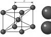
In Fig. Figure 23 shows the cube, the axes of rectangular coordinates x0, y0, z0 assigned to it, the projection plane P and axonometric image Cuba.


Fig.23. Education axonometric projections: a and b - frontal dimetric; c and d - isometric
Axonometry - a Greek word, translated means measurement along axes. When constructing axonometric projections, dimensions are laid along the x, y, z axes.
Axonometric projections are quite visual, so in a number of cases they are used to explain rectangular projections of complex machines and mechanisms and their individual parts. With axonometric projection, a figure is associated with a spatial system of coordinate axes, then this figure with the coordinate axes is projected onto one plane. This plane is called plane of axonometric projections.
Axonometric projections obtained by rectangular projection of a figure with coordinate axes, are called rectangular, and those obtained by oblique projection are called oblique.
Projection plane called the plane on which the projection of an object is obtained.