GOST 2.317-2011
Group T52
INTERSTATE STANDARD
Unified system of design documentation
AXONOMETRIC PROJECTIONS
Unified system of design documentation. Axonometric projections
ISS 01.100
OKSTU 0002
Date of introduction 2012-01-01
Preface
Preface
The goals, basic principles and basic procedure for carrying out work on interstate standardization are established in GOST 1.0-2015 "Interstate standardization system. Basic provisions" and GOST 1.2-2015 "Interstate standardization system. Interstate standards, rules and recommendations for interstate standardization. Rules for development, adoption , updates and cancellations"
Standard information
1 DEVELOPED by the Federal State Unitary Enterprise "All-Russian Research Institute of Standardization and Certification in Mechanical Engineering" (FSUE "VNIINMASH"), the Autonomous Non-Profit Organization "Research Center for CALS Technologies "Applied Logistics" (ANO Scientific Research Center for CALS Technologies "Applied Logistics" )
2 INTRODUCED by the Federal Agency for Technical Regulation and Metrology
3 ADOPTED by the Interstate Council for Standardization, Metrology and Certification (protocol dated May 12, 2011 N 39)
The following voted for the adoption of the standard:
Short name of the country according to MK (ISO 3166) 004-97 | Abbreviated name of the national standardization body |
|
Azerbaijan | Azstandard |
|
Ministry of Economy of the Republic of Armenia |
||
Belarus | State Standard of the Republic of Belarus |
|
Kazakhstan | Gosstandart of the Republic of Kazakhstan |
|
Kyrgyzstan | Kyrgyzstandard |
|
Moldova-Standard |
||
Rosstandart |
||
Tajikistan | Tajikstandard |
|
Uzbekistan | Uzstandard |
|
Gospotrebstandart of Ukraine |
4 By Order of the Federal Agency for Technical Regulation and Metrology dated August 3, 2011 N 211-st, the interstate standard GOST 2.317-2011 was put into effect as a national standard Russian Federation from January 1, 2012
5 INSTEAD GOST 2.317-69
6 REPUBLICATION. December 2018
Information about changes to this standard is published in the annual information index "National Standards", and the text of changes and amendments is published in the monthly information index "National Standards". In case of revision (replacement) or cancellation of this standard, the corresponding notice will be published in the monthly information index "National Standards". Relevant information, notices and texts are also posted in information system public use- on the official website Federal agency on technical regulation and metrology on the Internet (www.gost.ru)
1 Application area
This standard establishes axonometric projections used in graphic documents of all industries and construction.
Based on this standard, it is allowed, if necessary, to develop standards that take into account the specifics of performing axonometric projections in an organization.
2 Normative references
This standard uses normative references to the following interstate standards:
GOST 2.052-2015 Unified system of design documentation. Electronic model of the product. General provisions
GOST 2.102-2013 Unified system of design documentation. Types and completeness of design documents
GOST 2.311-68 Unified system of design documentation. Thread image
GOST 2.402-68 Unified system of design documentation. Legend gears, racks, worms and chain sprockets
Note - When using this standard, it is advisable to check the validity of the reference standards in the public information system - on the official website of the Federal Agency for Technical Regulation and Metrology on the Internet or using the annual information index "National Standards", which was published as of January 1 of the current year, and on issues of the monthly information index "National Standards" for the current year. If the reference standard is replaced (changed), then when using this standard you should be guided by the replacing (changed) standard. If the reference standard is canceled without replacement, then the provision in which a reference is made to it is applied in the part that does not affect this reference.
3 Terms and definitions
This standard uses terms according to GOST 2.052, as well as the following terms with corresponding definitions:
3.1 axonometric projection: Projection onto a plane using parallel rays, coming from the center of projection (which is removed to infinity) through each point of the object until it intersects with the plane onto which the object is projected.
3.3 oblique projection: An axonometric projection in which the projection direction is not perpendicular to the projection plane.
3.4 distortion factor: The ratio of the length of the projection of an axis segment onto a plane to its true length.
3.5 rectangular projection: An axonometric projection in which the projection direction is perpendicular to the projection plane.
3.6 electronic product model(model): Electronic model of a part or assembly unit in accordance with GOST 2.102.
4 Basic provisions
4.1 Depending on the direction of projection in relation to the projection plane, axonometric projections are divided into rectangular and oblique.
4.2 This standard establishes the rules for constructing (displaying) the following axonometric projections on the plane:
- rectangular isometric projection;
- rectangular dimetric projection;
- oblique frontal isometric projection;
- oblique horizontal isometric projection;
- oblique frontal dimetric projection.
4.3 The axonometric projections specified in this standard can be obtained by projection electronic model products on a plane in accordance with the requirements of this standard.
4.4 Hatching lines of sections in axonometric projections are drawn parallel to one of the diagonals of the projections of squares lying in the corresponding coordinate planes, the sides of which are parallel to the axonometric axes in accordance with Figure A.1 (Appendix A).
4.5 When applying dimensions, extension lines are drawn parallel to the axonometric axes, dimension lines are drawn parallel to the measured segment in accordance with Figure A.2 (Appendix A).
4.6 In axonometric projections, the spokes of flywheels and pulleys, stiffeners and similar elements are hatched (see Figure 6).
4.7 When making axonometric projections of gears, racks, worms and similar elements, it is allowed to apply conventions in accordance with GOST 2.402.
In axonometric projections, threads are depicted according to GOST 2.311.
It is allowed to depict the thread profile in whole or in part, as shown in Figure A.3 (Appendix A).
4.8 V necessary cases It is allowed to use other theoretically based axonometric projections.
5 Rectangular projections
5.1 Isometric projection
5.1.1 The position of the axonometric axes is shown in Figure 1.
5.1.2 The distortion coefficient along the , , axes is 0.82.
For simplification, an isometric projection is usually performed without distortion along the axes , , , i.e. taking the distortion factor equal to 1.
Figure 1
5.1.3 Circles lying in planes parallel to the projection planes are projected onto the axonometric plane of projections into ellipses (see Figure 2).
1 2 ; 3 - ellipse (major axis is located at an angle of 90° to the axis)
Figure 2
If an isometric projection is performed without distortion along the axes , , , then the major axis of the ellipses 1, 2, 3
If an isometric projection is performed with distortion along the axes , , , then the major axis of the ellipses 1, 2, 3
equal to the diameter of the circle, and the minor axis is 0.58 times the diameter of the circle.
5.1.4 An example of an isometric projection of a part is shown in Figure 3.
Figure 3
5.2 Dimetric projection
5.2.1 The position of the axonometric axes is shown in Figure 4.
Figure 4
5.2.2 The distortion coefficient along the axis is 0.47, and along the axes and is 0.94.
Dimetric projection, as a rule, is performed without distortion along the axes and and with a distortion coefficient of 0.5 along the axis.
5.2.3 Circles lying in planes parallel to the projection planes are projected onto the axonometric plane of projections into ellipses (see Figure 5).
1 - ellipse (the major axis is located at an angle of 90° to the axis); 2 - ellipse (the major axis is located at an angle of 90° to the axis); 3 - ellipse (major axis is located at an angle of 90° to the axis)
Figure 5
If a dimetric projection is performed without distortion along the and axes, then the major axis of the ellipses 1
, 2
, 3
equal to 1.06 times the diameter of the circle, and the minor axis of the ellipse 1
- 0.95, ellipses 2
And 3
- 0.35 circle diameter.
If a dimetric projection is performed with distortion along the and axes, then the major axis of the ellipses 1
, 2
, 3
equal to the diameter of the circle, and the minor axis of the ellipse 1
- 0.9, ellipses 2
And 3
- 0.33 circle diameter.
5.2.4 An example of a dimetric projection of a part is shown in Figure 6.
Figure 6
6 Oblique projections
6.1 Frontal isometric view
6.1.1 The position of the axonometric axes is shown in Figure 7.
Figure 7
It is allowed to use frontal isometric projections with an axis tilt angle of 30° and 60°.
6.1.2 The frontal isometric projection is performed without distortion along the axes , , .
6.1.3 Circles lying in planes parallel frontal plane projections are projected onto the axonometric plane in circles, and circles lying in planes parallel to the horizontal and profile planes of projections are projected into ellipses (see Figure 8).
1 - circle; 2 - ellipse (the major axis makes an angle of 22°30" with the axis); 3 - ellipse (the major axis makes an angle of 22°30") with the axis
Figure 8
Major axis of ellipses 2
And 3
is equal to 1.3, and the minor axis is 0.54 of the diameter of the circle.
6.1.4 An example of a frontal isometric projection of a part is shown in Figure 9.
Figure 9
6.2 Horizontal isometric projection
6.2.1 The position of the axonometric axes is shown in Figure 10.
Figure 10
It is allowed to use horizontal isometric projections with an axis tilt angle of 45° and 60°, while maintaining the angle between the axes and 90°.
6.2.2 Horizontal isometric projection is performed without distortion along the axes, and.
6.2.3 Circles lying in planes parallel horizontal plane projections are projected onto the axonometric plane of projections into circles, and circles lying in planes parallel to the frontal and profile planes of projections are projected into ellipses (see Figure 11).
1 - ellipse (the major axis makes an angle of 15° with the axis); 2 - circle; 3 - ellipse (the major axis makes an angle of 30° with the axis)
Figure 11
Major axis of the ellipse 1
is equal to 1.37, and the minor axis is 0.37 of the diameter of the circle.
Major axis of the ellipse 3
is equal to 1.22, and the minor axis is 0.71 times the diameter of the circle.
6.2.4 An example of a horizontal isometric projection is shown in Figure 12.
Figure 12
6.3 Frontal dimetric projection
6.3.1 The position of the axonometric axes is shown in Figure 13.
It is allowed to use frontal dimetric projections with an axis tilt angle of 30° and 60°.
The distortion coefficient along the axis is 0.5, and along the and axes - 1.
Figure 13
6.3.2 Circles lying in planes parallel to the frontal plane of projections are projected onto the axonometric plane of projections in circles, and circles lying in planes parallel to the horizontal and profile planes of projections are projected into ellipses (see Figure 14). Major axis of ellipses 2
And 3
is equal to 1.07, and the minor axis is 0.33 of the diameter of the circle.
1 - circle; 2 - ellipse (the major axis makes an angle of 7°14" with the axis); 3 - ellipse (the major axis makes an angle of 7°14") with the axis
Figure 14
6.3.3 An example of a frontal dimetric projection of a part is shown in Figure 15.
Figure 15
Appendix A (for reference). Conventions and sizing
Appendix A
(informative)
Figure A.1 - Drawing hatch lines in a section
Figure A.2 - Dimensions
Figure A.3 - Thread image
UDC 744.4:006.354 | |||
Key words: design documentation, rectangular projections, isometric projection, dimetric projection, oblique projections, frontal isometric projection, horizontal isometric projection, frontal dimetric projection |
|||
Electronic document text
prepared by Kodeks JSC and verified against:
official publication
M.: Standartinform, 2018
TO category:
Technical drawings
Frontal oblique dimetric projection
In the frontal oblique dimetric projection, the following position of the axonometric axes is accepted: the ox axis is directed horizontally; the oh axis is at an angle of 45° to the oh axis and the oz axis is vertical. The frontal projection of the object should be constructed along these axes. It is allowed to use the “left” arrangement of axes.
Linear dimensions parallel to the oy axis are plotted on a scale half as large as along the ox and oz axes. A characteristic feature of this type of axonometric projection is that figures parallel to the frontal plane of projections V are depicted without distortion. Therefore, such axonometric projections are called frontal. The construction of a frontal projection always begins with drawing axes, which are drawn with thin solid lines. The sequence of constructing frontal projections of some figures is shown in Fig. 2.

Rice. 1. Position of the axonometric axes: a - “right”; b - “left”.
If we place the axis of rotation of the cylinder parallel to the oz or oh axis, then its bases are projected in the form of ellipses.
The frontal dimetric projection of a cube with circles inscribed in its faces is shown in Fig. 34. The circle located on the front face of the cube is depicted without distortion, and the circles located on the top and side faces are depicted as ellipses same shape and sizes.
To construct an ellipse, eight points are found on the edges, which are then smoothly connected along the pattern. Four points are determined immediately - these are the midpoints of the sides of parallelograms representing the faces of the cube. Four other points are determined on the diagonals of the parallelograms by transferring them from the diagonals of the square.
To construct an ellipse on top edge first, on the front face of the cube, mark points 1 and 2 of the intersection of the diagonals of the square with the circle. Then straight lines are drawn from these points parallel to the oz axis to the top edge of the cube (the top side of the square). From the points obtained on the edge, straight lines are drawn parallel to the y axis until they intersect with the diagonals of the parallelogram. These will be the points of the ellipse.

Rice. 2. The sequence of constructing a frontal oblique dimetric projection: a - cube; b - cylinder; 8 - hexagonal prism.

Rice. 3. Frontal metric projection of a cube with circles inscribed in its faces.
Diagonal points are found similarly when constructing an ellipse on the side face of a cube. By connecting the found points with a smooth curve along the pattern, we obtain ellipses.
The angle of inclination of the major axis of the ellipse is approximately 7° with respect to the ox axis if the ellipse represents a circle on the top face of the cube, and with respect to the oz axis if the ellipse represents a circle on the side face of the cube. The minor axis of the ellipse is positioned perpendicular to the major one.
In practice, when constructing frontal projections of cylindrical parts, ovals rather than ellipses are usually drawn. The shape of an oval is close to the shape of an ellipse, but it is easier to draw it, since the construction is carried out with a compass according to the rules of conjugations.

Rice. 4. Constructing an oval on the top face of the cube.

Rice. 5. Rectangular projections models.
An oval on the upper face of the cube is constructed as follows: – draw the axonometric axes x, oy and oz; then from the center O - a circle with a diameter equal to the diameter of the circle shown in Fig. 34; – draw the major axis of the oval at an angle of 7° to the ox axis and the minor axis perpendicular to it. The extension of the minor axis intersects the circle at points O1 and 02; – from points Oi and,02, as from centers, draw auxiliary arcs with a radius of 001 equal to 002, until they intersect with the continuation of the minor axis at points 03 and 04, which are the centers of the large arcs of the oval; – draw straight lines 04L and 03B, which will intersect the major axis of the oval at points 06 and Ov, which are the centers of the small arcs of the oval; – from centers 03 and 04 large arcs of ovals are drawn with a radius of 04A equal to 03B; – small arcs are drawn from centers 08 and 06, closing the oval, with a radius ObA equal to OiB.
The construction of an oval - an approximate image of a circle - in the profile plane is similar.
Let's consider the construction of a frontal dimetric projection of the model according to the drawing shown in Fig. 5. First, draw the projection axes oh, oy and oz. Most characteristic appearance The model is a front view, so the construction of a frontal projection begins by drawing in the plane of the ox-oz axes the same image as the front view. In this plane, thin, barely noticeable lines mark a rectangle corresponding highest altitude and the width of the model. To do this, 60 mm (width of the model) is laid along the ox axis from point o to the left, and 40 mm (height of the model) along the oz axis upwards. From the obtained marks, straight lines are drawn, respectively, parallel to the ox and oz projection axes. A vertical center line is drawn in the middle of the overall rectangle.
In relation to this center line, the outline of the model is drawn in the overall rectangle, corresponding to the outline of its image in the front view. From corner points of the drawn contour, parallel straight lines are drawn at an angle of 45° with respect to the x axis, corresponding to the direction of the oy axis in the frontal projection.
On inclined straight lines, the thickness of the model is laid down, reduced by half, i.e. 50: 2 = 25 mm. The marks obtained on inclined straight lines are connected sequentially by straight lines, resulting in an image of the model in a frontal projection. All of these constructions are performed with thin, barely noticeable lines. Upon completion of construction, trace the resulting image contour lines and remove construction lines and invisible contour lines.

Rice. 6. Sequence of constructing a frontal dimetric projection of the model.

Rice. 7. Sequence of constructing the frontal dimetric projection of the bracket.
Axonometric drawings of machine parts and assemblies are often used in design documentation in order to clearly show the design features of a part (assembly unit) and to imagine what the part (assembly) looks like in space. Depending on the angle at which the coordinate axes are located, axonometric projections are divided into rectangular and oblique.
You will need
- Drawing program, pencil, paper, eraser, protractor.
Instructions
Rectangular projections. Isometric projection. When constructing a rectangular isometric projection, take into account the distortion coefficient along the X, Y, Z axes, equal to 0.82, while , parallel to the projection planes, are projected onto the axonometric projection planes in the form of ellipses, the axis of which is equal to d, and the axis is 0.58d, where d – diameter of the original circle. For ease of calculations, isometric projection without distortion along the axes (distortion coefficient is 1). In this case, the projected circles will look like ellipses with an axis equal to 1.22d and a minor axis equal to 0.71d.
Dimetric projection. When constructing a rectangular dimetric projection, the distortion coefficient along the X and Z axes is equal to 0.94, and along the Y axis – 0.47. To dimetric projection in a simplified manner, they are performed without distortion along the X and Z axes and with a distortion coefficient along the Y axis = 0.5. A circle parallel to the frontal projection plane is projected onto it in the form of an ellipse with a major axis equal to 1.06d and a minor axis equal to 0.95d, where d is the diameter of the original circle. Circles parallel to two other axonometric planes are projected onto them in the form of ellipses with axes equal to 1.06d and 0.35d, respectively.

Oblique projections. Frontal isometric view. When constructing a frontal isometric projection, the standard establishes the optimal angle of inclination of the Y axis to the horizontal at 45 degrees. Allowed angles of inclination of the Y axis to the horizontal are 30 and 60 degrees. The distortion coefficient along the X, Y and Z axes is 1. Circle 1, located on the frontal projection plane, is projected onto it without distortion. Circles parallel to the horizontal and profile planes of projections are made in the form of ellipses 2 and 3 with a major axis equal to 1.3d and a minor axis equal to 0.54d, where d is the diameter of the original circle.

Horizontal isometric projection. A horizontal isometric projection of a part (assembly) is built on axonometric axes located as shown in Fig. 7. It is allowed to change the angle between the Y axis and the horizontal by 45 and 60 degrees, leaving unchanged the angle of 90 degrees between the Y and X axes. The distortion coefficient along the X, Y, Z axes is 1. A circle lying in a plane parallel to the horizontal projection plane is projected as circle 2 without distortion. Circles parallel to the frontal and profile planes of projections, type of ellipses 1 and 3. The dimensions of the axes of the ellipses are related to the diameter d of the original circle by the following dependencies:
ellipse 1 – major axis is 1.37d, minor axis is 0.37d; ellipse 3 – major axis is 1.22d, minor axis is 0.71d.

Frontal dimetric projection. An oblique frontal dimetric projection of a part (assembly) is built on axonometric axes similar to the axes of the frontal isometric projection, but from it by a distortion coefficient along the Y axis, which is equal to 0.5. On the X and Z axes, the distortion coefficient is 1. It is also possible to change the angle of the Y axis to the horizontal to values of 30 and 60 degrees. A circle lying in a plane parallel to the frontal axonometric plane of projections is projected onto it without distortion. Circles parallel to the planes of horizontal and profile projections are drawn in the form of ellipses 2 and 3. The dimensions of the ellipses on the size of the diameter of the circle d are expressed by the dependence:
the major axis of ellipses 2 and 3 is 1.07d; the minor axis of ellipses 2 and 3 is 0.33d.

Video on the topic
Please note
Axonometric projection (from ancient Greek ἄξων “axis” and ancient Greek μετρέω “I measure”) is a way of depicting geometric objects in a drawing using parallel projections.
The plane onto which the projection is made is called axonometric or picture. An axonometric projection is called rectangular if, during parallel projection, the projecting rays are perpendicular to the picture plane (=90) and oblique if the rays make an angle of 0 with the picture plane
Sources:
- Handbook of Drawing
- axonometric projection of a circle
The image of an object in the drawing should give a complete idea of its shape and design features and can be done using rectangular projection, linear perspective and axonometric projection.

Instructions
Remember that dimetry is one of the types of axonometric projection of an object, in which the image is rigidly tied to the natural Oxyz coordinate system. Dimetry in that two distortion coefficients along the axes are equal and different from the third. Dimetry rectangular and frontal.
With rectangular diameter, the z axis is vertical, the x axis is c horizontal line the angle is 7011` and the y angle is 410 25`. The reduced distortion coefficient along the y-axis is ky = 0.5 (real 0.47), kx = kz = 1 (real 0.94). GOST 2.317–69 recommends using only the given coefficients when constructing images in a rectangular dimetric projection.
To draw a rectangular dimetric projection, mark on the drawing vertical axis Oz. To construct the x-axis, draw in the drawing a rectangle with legs 1 and 8 units, the vertex of which is point O. The hypotenuse of the rectangle will become the x-axis, which deviates from the horizon at an angle of 7011`. To construct the y-axis, also draw right triangle with the vertex at point O. The size of the legs in in this case 7 and 8 units. The resulting hypotenuse will be the y-axis, deviating from the horizon at an angle of 410 25`.
When constructing a dimetric projection, the size of the object is increased by 1.06 times. In this case, the image is projected into an ellipse in the coordinate planes xOy and yO with major axis, equal to 1.06d, where d is the diameter of the projected circle. The minor axis of the ellipse is 0.35 d.
Video on the topic
Please note
Many industries use drawings. The rules for depicting objects and drawing up drawings are regulated by the “Unified System of Design Documentation” (ESKD).
To make any part, you need to design it and produce drawings. The drawing should show the main and auxiliary views of the part, which, when read correctly, give the entire necessary information about the shape and size of the product.

Instructions
How, designing new parts, studying state and industry standards according to which design documentation is carried out. Find all GOSTs and OSTs that will be needed when drawing a part. To do this, you need standards numbers by which you can find them on the Internet in electronic form or in the company archive in paper form.
Before you start drawing, select the required sheet on which it will be located. Consider the number of projections of the part that you need to depict in the drawing. For parts of simple shape (especially for bodies of revolution), the main view and one projection are sufficient. If the designed part has complex shape, large number through and blind holes, grooves, it is advisable to make several projections, as well as provide additional local views.
Draw main view details. Choose the view that will give the most complete idea of the shape of the part. Make other views if necessary. Draw cuts and sections showing the internal holes and grooves of the part.
Apply dimensions in accordance with GOST 2.307-68. Overall dimensions are better than the size of the part, so put these dimensions so that they can be easily identified on the drawing. Enter all dimensions with tolerances or indicate the quality according to which the part should be manufactured. Remember that in real life, produce a part with exact dimensions. There will always be a deviation upward or downward, which should be within the tolerance range for the size.
Be sure to indicate the surface roughness of the part in accordance with GOST 2.309-73. This is very important, especially for precision instrument-making parts that are part of assembly units and are connected by fit.
Write down the technical requirements for the part. Indicate its manufacture, processing, coating, operation and storage. In the title block of the drawing, do not forget to indicate the material from which the part is made.
Video on the topic
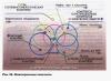
When designing and practically debugging power supply systems, you have to use various schemes. Sometimes they are given in finished form, attached to technical system, but in some cases you have to draw the diagram yourself, restoring it based on installation and connections. How accessible it will be to understand depends on the correct drawing of the diagram.

Instructions
Use to draw a power supply diagram computer program"Visio". For accumulation, you can first diagram an abstract supply circuit, including an arbitrary set of elements. In accordance with the standards and requirements of the unified design system, the principal design is drawn in a single-line image.
Select Page Options settings. In the “File” menu, use the appropriate command, and in the window that opens, set the required format for the future image, for example, A3 or A4. Also select portrait or landscape drawing orientation. Set the scale to 1:1, and the unit of measurement to millimeters. Complete your selection by clicking on the “OK” button.
Using the "Open" menu, find the stencil library. Open the set of main inscriptions and transfer the frame, inscription shape and additional columns to the sheet of the future drawing. Fill in the necessary columns that explain the diagram.
Draw the actual supply circuit diagram using stencils from the program, or use other blanks at your disposal. Convenient to use a specially designed drawing kit electrical diagrams various supply circuits.
Since many components of the power circuit separate groups are often of the same type, draw similar ones by copying already drawn elements, and then make adjustments. In this case, select the elements of the group with the mouse and move the copied fragment to the desired place in the diagram.
Finally, move the input circuit components from the stencil set. Carefully fill out the explanatory notes for the diagram. Save the changes with the desired name. If necessary, print the completed power supply diagram.
Constructing an isometric projection of a part allows you to obtain the most detailed understanding of the spatial characteristics of the image object. Isometric with cutout of part of the part in addition to appearance shows internal structure subject.

You will need
- - a set of drawing pencils;
- - ruler;
- - squares;
- - protractor;
- - compass;
- - eraser.
Instructions
Draw the axes with thin lines so that the image is located in the center of the sheet. In a rectangular isometry The angles between the axes are one hundred degrees. In a horizontal oblique isometry the angles between the X and Y axes are ninety degrees. And between the X and Z axes; Y and Z - one hundred thirty-five degrees.
Start with top surface depicted detail. Draw vertical lines down from the corners of the horizontal surfaces and mark the corresponding linear dimensions from the part drawing on these lines. IN isometry linear dimensions along all three axes remain unity. Consistently connect the resulting points to vertical lines. The outer contour of the part is ready. Draw images of holes, grooves, etc. on the edges of the part.
Remember that when depicting objects in isometry the visibility of curved elements will be distorted. Circumference in isometry is depicted as an ellipse. Distance between ellipse points along axes isometry equal to the diameter of the circle, and the axes of the ellipse do not coincide with the axes isometry.
All actions must be performed using drawing tools - ruler, pencil, compass and protractor. Use several pencils of different hardnesses. Hard - for thin lines, hard - for dotted and dash-dotted lines, soft - for main lines. Do not forget to draw and fill out the main inscription and frame in accordance with GOST. Also construction isometry can be performed in a specialized software, such as Compass, AutoCAD.
Sources:
- isometric drawing
There are not many people these days who have never had to draw or draw something on paper in their lives. The ability to make a simple drawing of any design is sometimes very useful. You can spend a lot of time explaining “on your fingers” how this or that thing is made, while one glance at its drawing is enough to understand it without any words.

You will need
- – sheet of whatman paper;
- – drawing accessories;
- - drawing board.
Instructions
Select the sheet format on which the drawing will be drawn - in accordance with GOST 9327-60. The format should be such that the main information can be placed on the sheet species details in the appropriate scale, as well as all necessary cuts and sections. For simple parts, choose A4 (210x297 mm) or A3 (297x420 mm) format. The first can be positioned with its long side only vertically, the second - vertically and horizontally.
Draw a frame for the drawing, 20 mm from the left edge of the sheet, 5 mm from the other three. Draw the main inscription - a table in which all data about details and drawing. Its dimensions are determined by GOST 2.108-68. The width of the main inscription remains unchanged - 185 mm, the height varies from 15 to 55 mm depending on the purpose of the drawing and the type of institution for which it is being carried out.
Select the main image scale. Possible scales are determined by GOST 2.302-68. They should be chosen so that all the main elements are clearly visible in the drawing. details. If some places are not visible clearly enough, they can be taken out a separate species, shown with the necessary magnification.
Select main image details. It should represent the direction of view of the part (direction of projection) from which its design is most fully revealed. In most cases, the main image is the position in which the part is on the machine during the main operation. Parts that have an axis of rotation are located on the main image, as a rule, so that the axis has horizontal position. The main image is located at the top left of the drawing (if there are three projections) or close to the center (if there is no side projection).
Determine the location of the remaining images (side view, top view, sections, sections). Species details are formed by its projection onto three or two mutually perpendicular planes(Monge method). In this case, the part must be positioned in such a way that most or all of its elements are projected without distortion. If any of these types is informationally redundant, do not perform it. The drawing should have only those images that are necessary.
Select the cuts and sections to be made. Their difference from each other is that it also shows what is located behind the cutting plane, while the section displays only what is located in the plane itself. The cutting plane can be stepped or broken.
Proceed directly to drawing. When drawing lines, follow GOST 2.303-68, which defines species lines and their parameters. Place the images at such a distance from each other that there is enough space for dimensioning. If the cutting planes pass along the monolith details, hatch the sections with lines running at an angle of 45°. If the hatch lines coincide with the main lines of the image, you can draw them at an angle of 30° or 60°.
Draw dimension lines and mark down the dimensions. In doing so, be guided the following rules. The distance from the first dimension line to the outline of the image must be at least 10 mm, the distance between adjacent dimension lines must be at least 7 mm. The arrows should be about 5 mm long. Write numbers in accordance with GOST 2.304-68, take their height to be 3.5-5 mm. Place the numbers closer to the middle of the dimension line (but not on the image axis) with some offset relative to the numbers placed on adjacent dimension lines.
Video on the topic
Sources:
The ratio of angles and planes of any object visually changes depending on the object’s position in space. That is why the part in the drawing is usually performed in three orthogonal projections, to which a spatial image is added. Usually this is . When performing it, vanishing points are not used, as when constructing a frontal perspective. Therefore, the dimensions do not change as they move away from the observer.

You will need
- - ruler;
- - compass;
- - a sheet of paper.
Instructions
Define the axes. To do this, draw a circle of arbitrary radius from point O. Central angle its equal to 360º. Divide the circle into 3 equal ones, using the OZ axis as the base radius. In this case, the angle of each sector will be equal to 120º. The two radii exactly represent the OX and OY axes you need.
Determine the position. Divide the angles between the axes in half. Connect point O to these new points with thin lines. Center position circle depends on conditions. Mark it with a dot and draw a perpendicular to it in both directions. This line will determine the position of the large diameter.
Calculate the diameters. They depend on whether you apply a distortion factor or not. This coefficient for all axes is 0.82, but quite often it is rounded and taken as 1. Taking into account the distortion, the major and minor diameters of the ellipse are 1 and 0.58 of the original, respectively. Without applying the coefficient, these dimensions are 1.22 and 0.71 of the diameter of the original circle.
Video on the topic
Please note
To create a three-dimensional image, you can construct not only isometric, but also dimetric projection, as well as frontal or linear perspective. Projections are used in detail drawings, while perspectives are used primarily in architecture. A circle in dimetry is also depicted as an ellipse, but there is a different arrangement of axes and different distortion coefficients. When executing various types perspectives take into account changes in size with distance from the observer.
Oblique dimetric projection (frontal)
If you place coordinate axes X And Y parallel to the P¢ plane, then the distortion indicators along these axes will become equal to one (k = t=1). Axis distortion index Y usually taken equal to 0.5. Axonometric axes X" And Z" make a right angle, axis Y" usually drawn as the bisector of this angle. Axis X can be directed either to the right of the axis Z", and to the left.
Preferably use right system, since it is more convenient to depict objects in dissected form. In this type of axonometry, it is good to draw parts that have the shape of a cylinder or cone.

For the convenience of depicting this part, the axis Y must be aligned with the axis of rotation of the cylinder surfaces. Then all circles will be depicted in natural size, and the length of each surface will be halved (Fig. 10.21).

Inclined sections.
When making drawings of machine parts, it is often necessary to use inclined sections.
When solving such problems, it is necessary first of all to understand: how the cutting plane should be located and which surfaces are involved in the section in order for the part to be read better. Let's look at examples.
Given a tetrahedral pyramid, which is dissected by an inclined frontally projecting plane A-A(Fig. 11.1). The cross section will be a quadrilateral.

First we construct its projections onto P 1 and on P 2. The frontal projection coincides with the projection of the plane, and we construct the horizontal projection of the quadrangle according to its membership in the pyramid.
Then we construct the natural size of the section. To do this, an additional projection plane is introduced P 4, parallel to a given cutting plane A-A, we project a quadrilateral onto it, and then combine it with the drawing plane.
This is the fourth main task of converting a complex drawing (module No. 4, p. 15 or task No. 117 from workbook in descriptive geometry).
Constructions are carried out in the following sequence (Fig. 11.2):
1. 1.On free space draw the center line of the drawing, parallel to the plane A-A.
2. 2. From the points of intersection of the edges of the pyramid with the plane, we draw projecting rays perpendicular to the cutting plane. Points 1 And 3 will lie on a line perpendicular to the axial one.
3. 3.Distance between points 2 And 4 transferred from horizontal projection.
4. Similarly, the true size of the section of the surface of revolution is constructed - an ellipse.

Distance between points 1 And 5 -major axis of the ellipse. The minor axis of the ellipse must be constructed by dividing the major axis in half ( 3-3 ).
Distance between points 2-2, 3-3, 4-4 transferred from horizontal projection.
Let's consider more complex example, including polyhedral surfaces and surfaces of revolution (Fig. 11.3)
A tetrahedral prism is specified. There are two holes in it: a prismatic one, located horizontally, and a cylindrical one, the axis of which coincides with the height of the prism.
The cutting plane is front-projecting, so the frontal projection of the section coincides with the projection of this plane.
Quadrangular prism projecting to the horizontal plane of projections, and therefore the horizontal projection of the section is also in the drawing, it coincides with the horizontal projection of the prism.
The actual size of the section into which both prisms and the cylinder fall is constructed on a plane parallel to the cutting plane A-A(Fig. 11.3).
Execution Sequence inclined section:
1. The section axis is drawn parallel to the cutting plane on the free field of the drawing.
2. A cross-section of the external prism is constructed: its length is transferred from the frontal projection, and the distance between the points from the horizontal one.
In order to obtain an axonometric projection of an object (Fig. 106), it is necessary to mentally: place the object in the coordinate system; select an axonometric projection plane and place the object in front of it; choose the direction of parallel projecting rays, which should not coincide with any of the axonometric axes; direct the projecting rays through all points of the object and coordinate axes until they intersect with the axonometric plane of projections, thereby obtaining an image of the projected object and coordinate axes.
On the axonometric plane of projections, an image is obtained - an axonometric projection of an object, as well as projections of the axes of coordinate systems, which are called axonometric axes.
An axonometric projection is an image obtained on an axonometric plane as a result of parallel projection of an object along with a coordinate system, which visually displays its shape.
The coordinate system consists of three mutually intersecting planes that have a fixed point - the origin (point O) and three axes (X, Y, Z) emanating from it and located at right angles to each other. The coordinate system allows you to make measurements along the axes, determining the position of objects in space.
Rice. 106. Obtaining an axonometric (rectangular isometric) projection
Many axonometric projections can be obtained, differently placing the object in front of the plane and choosing different direction projecting rays (Fig. 107).
The most commonly used is the so-called rectangular isometric projection (in the future we will use its abbreviated name - isometric projection). An isometric projection (see Fig. 107, a) is a projection in which the distortion coefficients along all three axes are equal, and the angles between the axonometric axes are 120°. An isometric projection is obtained using parallel projection.

Rice. 107. Axonometric projections established by GOST 2.317-69:
a - rectangular isometric projection; b - rectangular dimetric projection;
c - oblique frontal isometric projection;
d - oblique frontal dimetric projection

Rice. 107. Continued: d - oblique horizontal isometric projection
In this case, the projecting rays are perpendicular to the axonometric plane of projections, and the coordinate axes are equally inclined to the axonometric plane of projections (see Fig. 106). If we compare the linear dimensions of an object and the corresponding dimensions axonometric image, then you can see that in the image these dimensions are smaller than the actual ones. Values showing the ratio of the sizes of projections of straight segments to their actual sizes are called distortion coefficients. The distortion coefficients (K) along the axes of the isometric projection are the same and equal to 0.82, however, for ease of construction, the so-called practical distortion coefficients are used, which are equal to unity (Fig. 108).

Rice. 108. Position of axes and coefficients of distortion of isometric projection
There are isometric, dimetric and trimetric projections. TO isometric projections These include projections that have the same distortion coefficients on all three axes. Dimetric projections are those projections in which two coefficients of distortion along the axes are the same, and the value of the third differs from them. Trimetric projections are projections in which all distortion coefficients are different.