Determining the center of gravity arbitrary body by sequential addition of forces acting on its individual parts - difficult task; it becomes easier only for bodies of relatively simple shape.
Let the body consist of only two masses and connected by a rod (Fig. 125). If the mass of the rod is small compared to the masses and , then it can be neglected. Each of the masses is acted upon by gravity forces equal to and respectively; both of them are directed vertically downwards, i.e. parallel to each other. As we know, the resultant of two parallel forces applied at point, which is determined from the condition

Rice. 125. Determination of the center of gravity of a body consisting of two loads
Consequently, the center of gravity divides the distance between two loads in a ratio inverse to the ratio of their masses. If this body is suspended at point , it will remain in equilibrium.
Since two equal masses have common center gravity at a point bisecting the distance between these masses, it is immediately clear that, for example, the center of gravity of a homogeneous rod lies in the middle of the rod (Fig. 126).
Since any diameter is uniform round disk divides it into two completely identical symmetrical parts (Fig. 127), then the center of gravity should lie on each diameter of the disk, i.e. at the point of intersection of the diameters - at geometric center disk Reasoning in a similar way, we can find that the center of gravity homogeneous ball lies at its geometric center, the center of gravity of a uniform rectangular parallelepiped lies at the intersection of its diagonals, etc. The center of gravity of a hoop or ring lies at its center. Last example shows that the center of gravity of a body can lie outside the body.

Rice. 126. The center of gravity of a homogeneous rod lies in its middle

Rice. 127. The center of a homogeneous disk lies at its geometric center
If the body has an irregular shape or if it is heterogeneous (for example, it has voids), then calculating the position of the center of gravity is often difficult and it is more convenient to find this position through experiment. Let, for example, you want to find the center of gravity of a piece of plywood. Let's hang it on a thread (Fig. 128). Obviously, in the equilibrium position, the center of gravity of the body must lie on the extension of the thread, otherwise the force of gravity will have a moment relative to the point of suspension, which would begin to rotate the body. Therefore, by drawing a straight line on our piece of plywood, representing the continuation of the thread, we can say that the center of gravity lies on this straight line.
Indeed, hanging the body in different points and by drawing vertical lines, we will make sure that they all intersect at one point. This point is the center of gravity of the body (since it must lie simultaneously on all such lines). In this way, you can determine the position of the center of gravity not only flat figure, but also a more complex body. The position of the aircraft's center of gravity is determined by rolling its wheels onto the weighing platform. The resultant of the weight forces exerted on each wheel will be directed vertically, and the line along which it acts can be found using the law of addition of parallel forces.

Rice. 128. The point of intersection of vertical lines drawn through the suspension points is the center of gravity of the body
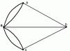
When changing masses individual parts body or when the shape of the body changes, the position of the center of gravity changes. Thus, the center of gravity of the aircraft moves when fuel is consumed from the tanks, when loading luggage, etc. For a visual experiment illustrating the movement of the center of gravity when the shape of the body changes, it is convenient to take two identical bars connected by a hinge (Fig. 129). In the case when the bars form a continuation of one another, the center of gravity lies on the axis of the bars. If the bars are bent at a hinge, then the center of gravity is outside the bars, on the bisector of the angle they form. If you put an additional load on one of the bars, the center of gravity will move towards this load.

Rice. 129. a) The center of gravity of bars connected by a hinge, located on one straight line, lies on the axis of the bars, b) The center of gravity of a bent system of bars lies outside the bars
81.1. Where is the center of gravity of two identical thin rods having a length of 12 cm and fastened in the shape of the letter T?
81.2. Prove that the center of gravity of a homogeneous triangular plate lies at the intersection of the medians.

Rice. 130. For exercise 81.3
81.3. A homogeneous board of mass 60 kg rests on two supports, as shown in Fig. 130. Determine the forces acting on the supports.
The MatLab package allows you to display graphs with different colors and line type, show or hide the grid on the graph, label axes and the graph as a whole, create a legend and much more. In this section, we will consider the most important functions that allow you to make such designs using the example of two-dimensional charts.
The plot() function allows you to change the color and type of line displayed. For this, additional parameters are used, which are written as follows:
plot(
Please note that the third parameter is written in apostrophes and has the notation given in tables 3.1-3.3. The markers below are written in a row one after another, for example,
‘ko’ – displays the graph points in black circles on the graph,
‘ko-‘ – draws a graph with a black line and places dots in the form of circles.
Table 3.1. Graph line color designation
|
Line color |
|
|
violet |
|
Table 3.2. Graph line type designation
|
Line color |
|
|
continuous |
|
|
dashed |
|
|
dotted |
|
|
dash-dotted |
Table 3.3. Designation of the type of graph points
|
Line color |
|
|
star |
|
Below are examples of writing the plot() function with a different set of markers.
x = 0:0.1:2*pi;
y = sin(x);
subplot(2,2,1); plot(x,y,"r-");
subplot(2,2,2); plot(x,y,"r-",x,y,"ko");
subplot(2,2,3); plot(y,"b--");
subplot(2,2,4); plot(y,"b--+");
The result of the program fragment is shown in Fig. 3.7. The example presented shows how markers can be combined to achieve the desired result. And in Fig. 3.7 clearly shows what visual effects the different markers used in the program lead to. It should be especially noted that in the fourth line of the program, two graphs are essentially displayed: the first is drawn in red and a continuous line, and the second in black circles given points graphics. The remaining options for recording markers are obvious.
Rice. 3.7. Examples of displaying graphs with different types of markers
From the examples in Fig. 3.7 it is clear that the scale of the graphs along the Ox axis is slightly larger than the real values. The fact is that the MatLab system automatically scales the coordinate system to fully represent the data. However, such automatic configuration may not always satisfy the user's interests. Sometimes you need to select a separate fragment of the graph and only show it in its entirety. To do this, use the axis() function of the MatLab language, which has the following syntax:
axis([ xmin, xmax, ymin, ymax ]),
where the names of the specified parameters speak for themselves.
Let's use this function to display a graph of the sine function ranging from 0 to :
x = 0:0.1:2*pi;
y = sin(x);
subplot(1,2,1);
plot(x,y);
axis();
subplot(1,2,2);
plot(x,y);
axis();
From the result of the program (Fig. 3.8) it is clear that despite the fact that the sine function is specified in the range from 0 to , using the axis() function you can display both the entire graph and its fragment in the range from 0 to .

Rice. 3.8. An example of how the axis() function works
In conclusion of this section, we will consider the possibilities of creating graph labels, axes and displaying a grid on a graph. To do this, use the functions of the MatLab language listed in table. 3.4.
Table 3.4. Chart design functions
|
Name |
Description |
|
Enables/disables the grid on the chart |
|
|
title('graph title') |
Creates a graph title label |
|
xlabel('Ox axis label') |
Creates an Ox axis label |
|
ylabel(‘Oy axis label’) |
Creates the Oy axis label |
|
text(x,y,’text’) |
Creates a text label at (x,y) coordinates. |
Let's look at how these functions work in the following example:
x = 0:0.1:2*pi;
y = sin(x);
plot(x,y);
axis();
grid on;
title("The graphic of sin(x) function");
xlabel("The coordinate of Ox");
ylabel("The coordinate of Oy");
text(3.05,0.16,"\leftarrow sin(x)");
From the result of this program, presented in Fig. 3.9, you can see how the functions of creating labels on a chart work, as well as displaying a chart grid.
Thus, using the described set of functions and parameters, you can achieve desired method design of graphs in the MatLab system.

Rice. 3.9. An example of how chart design functions work