When connecting to two parallel conductors electric current, they will attract or repel, depending on the direction (polarity) of the connected current. This is explained by the phenomenon of the emergence of a special kind of matter around these conductors. This matter is called a magnetic field (MF). Magnetic force is the force with which conductors act on each other.
The theory of magnetism arose in ancient times, in ancient civilization Asia. In the mountains of Magnesia they found a special rock, pieces of which could be attracted to each other. Based on the name of the place, this rock was called “magnetic”. A bar magnet contains two poles. Its magnetic properties are especially pronounced at the poles.
A magnet hanging on a thread will show the sides of the horizon with its poles. Its poles will be turned north and south. The compass device operates on this principle. Opposite poles of two magnets attract, and like poles repel.
Scientists have discovered that a magnetized needle located near a conductor is deflected when an electric current passes through it. This indicates that an MP is formed around it.
The magnetic field affects:
Moving electric charges.
Substances called ferromagnets: iron, cast iron, their alloys.
Permanent magnets– bodies that have a common magnetic moment of charged particles (electrons).
1 - South pole of the magnet
2 — North Pole magnet
3 - MP using the example of metal filings
4 - Magnetic field direction
Lines of force appear when a permanent magnet approaches a paper sheet on which a layer is poured iron filings. The figure clearly shows the locations of the poles with oriented lines of force.
Magnetic field sources
- Electric field changing over time.
- Mobile charges.
- Permanent magnets.
We have been familiar with permanent magnets since childhood. They were used as toys that attracted various metal parts. They were attached to the refrigerator, they were built into various toys.
Electric charges that are in motion most often have more magnetic energy compared to permanent magnets.
Properties
- Main hallmark and the property of the magnetic field is relativity. If you leave a charged body motionless in a certain frame of reference, and place a magnetic needle nearby, then it will point to the north, and at the same time will not “feel” an extraneous field, except for the field of the earth. And if you start moving a charged body near the arrow, then an MP will appear around the body. As a result, it becomes clear that the MF is formed only when a certain charge moves.
- A magnetic field can influence and influence electric current. It can be detected by monitoring the movement of charged electrons. In a magnetic field, particles with a charge will be deflected, conductors with current flowing will move. The frame with the current supply connected will begin to rotate, and the magnetized materials will move a certain distance. The compass needle is most often colored blue. It is a strip of magnetized steel. The compass always points north, since the Earth has a magnetic field. The entire planet is like a big magnet with its own poles.
The magnetic field is not perceived by human organs and can only be detected by special devices and sensors. It can be variable and permanent type. The alternating field is usually created by special inductors that operate from AC. A constant field is formed by a constant electric field.
Rules
Let's consider the basic rules for depicting the magnetic field for various conductors.
Gimlet rule
The line of force is depicted in a plane, which is located at an angle of 90 0 to the path of current flow so that at each point the force is directed tangentially to the line.
To determine the direction of magnetic forces, you need to remember the rule of a gimlet with a right-hand thread.

The gimlet must be positioned along the same axis with the current vector, the handle must be rotated so that the gimlet moves in the direction of its direction. In this case, the orientation of the lines is determined by rotating the gimlet handle.
Ring gimlet rule
The translational movement of the gimlet in a conductor made in the form of a ring shows how the induction is oriented; the rotation coincides with the flow of current.

The lines of force have their continuation inside the magnet and cannot be open.
Magnetic field different sources are summed up with each other. In doing so, they create a common field.
Magnets with the same poles repel, and magnets with different poles attract. The value of the interaction strength depends on the distance between them. As the poles approach, the force increases.
Magnetic field parameters
- Flow coupling ( Ψ ).
- Magnetic induction vector ( IN).
- Magnetic flux ( F).
The intensity of the magnetic field is calculated by the size of the magnetic induction vector, which depends on the force F, and is formed by the current I along a conductor having a length l: B = F / (I * l).
Magnetic induction is measured in Tesla (T), in honor of the scientist who studied the phenomena of magnetism and worked on their calculation methods. 1 T is equal to induction magnetic flux by force 1 N at length 1 m straight conductor, located at an angle 90 0 to the direction of the field, with a flowing current of one ampere:
1 T = 1 x H / (A x m).
Left hand rule
The rule finds the direction of the magnetic induction vector.

If the palm of the left hand is placed in the field so that the magnetic field lines enter the palm from the north pole at 90 0, and 4 fingers are placed along the current flow, thumb will show the direction of the magnetic force.
If the conductor is at a different angle, then the force will directly depend on the current and the projection of the conductor onto the plane at a right angle.
The force does not depend on the type of conductor material and its cross-section. If there is no conductor, and the charges move in a different medium, then the force will not change.
When the magnetic field vector is directed in one direction of one magnitude, the field is called uniform. Various environments affect the size of the induction vector.
Magnetic flux
Magnetic induction passing through a certain area S and limited by this area is a magnetic flux.

If the area is inclined at a certain angle α to the induction line, the magnetic flux is reduced by the size of the cosine of this angle. Its greatest value is formed when the area is at right angles to the magnetic induction:
F = B * S.
Magnetic flux is measured in a unit such as "weber", which is equal to the flow of induction of magnitude 1 T by area in 1 m2.
Flux linkage
This concept is used to create general meaning magnetic flux, which is created from a certain number of conductors located between the magnetic poles.
In the case where the same current I flows through a winding with a number of turns n, the total magnetic flux formed by all turns is the flux linkage.

Flux linkage Ψ measured in Webers, and equals: Ψ = n * Ф.
Magnetic properties
Magnetic permeability determines how much the magnetic field in a certain medium is lower or higher than the field induction in a vacuum. A substance is called magnetized if it produces its own magnetic field. When a substance is placed in a magnetic field, it becomes magnetized.
Scientists have determined the reason why bodies acquire magnetic properties. According to scientists' hypothesis, there are microscopic electric currents inside substances. The electron has its own magnetic moment, which has quantum nature, moves along a certain orbit in atoms. It is these small currents that determine magnetic properties.
If the currents move randomly, then the magnetic fields caused by them are self-compensating. The external field makes the currents ordered, so a magnetic field is formed. This is the magnetization of the substance.
Various substances can be divided according to the properties of their interaction with magnetic fields.
They are divided into groups:
Paramagnets– substances that have magnetization properties in the direction external field, having a low potential for magnetism. They have a positive field strength. Such substances include ferric chloride, manganese, platinum, etc.
Ferrimagnets– substances with magnetic moments unbalanced in direction and value. They are characterized by the presence of uncompensated antiferromagnetism. Field strength and temperature affect their magnetic susceptibility (various oxides).
Ferromagnets– substances with increased positive susceptibility, depending on tension and temperature (crystals of cobalt, nickel, etc.).
Diamagnets– have the property of magnetization in opposite direction external field, that is, negative value magnetic susceptibility, independent of tension. In the absence of a field, this substance will not have magnetic properties. These substances include: silver, bismuth, nitrogen, zinc, hydrogen and other substances.
Antiferromagnets
– have a balanced magnetic moment, resulting in a low degree of magnetization of the substance. When heated, they carry out phase transition a substance that produces paramagnetic properties. When the temperature drops below a certain limit, such properties will not appear (chrome, manganese).
The magnets considered are also classified into two more categories:
Soft magnetic materials
. They have low coercivity. In low-power magnetic fields they can become saturated. During the magnetization reversal process, they experience minor losses. As a result, such materials are used for the production of cores of electrical devices operating on alternating voltage (, generator,).
Hard magnetic materials. They have an increased coercive force. To remagnetize them, a strong magnetic field is required. Such materials are used in the production of permanent magnets.
Magnetic properties various substances find their use in technical projects and inventions.
Magnetic circuits
Combining several magnetic substances called a magnetic circuit. They are similar and are determined by similar laws of mathematics.
Operate on the basis of magnetic circuits electrical appliances, inductance, . In a functioning electromagnet, the flux flows through a magnetic circuit made of ferromagnetic material and air, which is not ferromagnetic. The combination of these components is a magnetic circuit. Many electrical devices contain in their design magnetic circuits.
To understand what is a characteristic of a magnetic field, many phenomena must be defined. At the same time, you need to remember in advance how and why it appears. Find out what is the strength characteristic of a magnetic field. It is important that such a field can occur not only in magnets. In this regard, it would not hurt to mention the characteristics of the earth’s magnetic field.
Emergence of the field
To begin with, we should describe the emergence of the field. Then you can describe the magnetic field and its characteristics. It appears during the movement of charged particles. May affect in particular live conductors. The interaction between a magnetic field and moving charges, or conductors through which current flows, occurs due to forces called electromagnetic.
Intensity or power characteristic magnetic field in a certain spatial point determined using magnetic induction. The latter is designated by the symbol B.
Graphical representation of the field
The magnetic field and its characteristics can be presented in graphic form using induction lines. This definition refers to lines whose tangents at any point will coincide with the direction of the magnetic induction vector.
These lines are included in the characteristics of the magnetic field and are used to determine its direction and intensity. The higher the intensity of the magnetic field, the more of these lines will be drawn.
What are magnetic lines
Magnetic lines straight conductors with current have the shape of a concentric circle, the center of which is located on the axis of a given conductor. The direction of magnetic lines near conductors carrying current is determined by the gimlet rule, which sounds like this: if the gimlet is positioned so that it is screwed into the conductor in the direction of the current, then the direction of rotation of the handle corresponds to the direction of the magnetic lines.

In a coil with current, the direction of the magnetic field will also be determined by the gimlet rule. It is also required to rotate the handle in the direction of the current in the solenoid turns. The direction of the magnetic induction lines will correspond to the direction forward motion gimlet.
It is the main characteristic of a magnetic field.
Created by one current, at equal conditions, the field will vary in intensity in different environments due to the different magnetic properties in these substances. The magnetic properties of the medium are characterized by absolute magnetic permeability. It is measured in henry per meter (g/m).
The characteristic of the magnetic field includes the absolute magnetic permeability of the vacuum, called the magnetic constant. The value that determines how many times the absolute magnetic permeability of the medium will differ from the constant is called relative magnetic permeability.
Magnetic permeability of substances
This is a dimensionless quantity. Substances with a permeability value less than one are called diamagnetic. In these substances the field will be weaker than in a vacuum. These properties are present in hydrogen, water, quartz, silver, etc.
Media with a magnetic permeability exceeding unity are called paramagnetic. In these substances the field will be stronger than in a vacuum. These media and substances include air, aluminum, oxygen, and platinum.

In the case of paramagnetic and diamagnetic substances, the value of magnetic permeability will not depend on the voltage of the external, magnetizing field. This means that the quantity is constant for a certain substance.
Ferromagnets belong to a special group. For these substances, the magnetic permeability will reach several thousand or more. These substances, which have the property of being magnetized and enhancing a magnetic field, are widely used in electrical engineering.
Field strength
To determine the characteristics of a magnetic field, a value called magnetic field strength can be used along with the magnetic induction vector. This term is determining the intensity of the external magnetic field. The direction of the magnetic field in a medium with identical properties in all directions the intensity vector will coincide with the magnetic induction vector at the field point.
The strength of ferromagnets is explained by the presence in them of arbitrarily magnetized small parts, which can be represented in the form of small magnets.

With no magnetic field, a ferromagnetic substance may not have pronounced magnetic properties, since the fields of the domains acquire different orientations, and their total magnetic field is zero.
According to the main characteristic of the magnetic field, if a ferromagnet is placed in an external magnetic field, for example, in a coil with current, then under the influence of the external field the domains will turn in the direction of the external field. Moreover, the magnetic field at the coil will increase, and the magnetic induction will increase. If the external field is weak enough, then only a part of all domains will turn over, the magnetic fields of which are close in direction to the direction of the external field. As the strength of the external field increases, the number of rotated domains will increase, and at a certain value of the external field voltage, almost all parts will be rotated so that the magnetic fields are located in the direction of the external field. This condition called magnetic saturation.
Relationship between magnetic induction and tension
The relationship between the magnetic induction of a ferromagnetic substance and the external field strength can be depicted using a graph called a magnetization curve. At the point where the curve graph bends, the rate of increase in magnetic induction decreases. After bending, where the tension reaches a certain value, saturation occurs, and the curve rises slightly, gradually taking on the shape of a straight line. In this area, the induction is still growing, but rather slowly and only due to an increase in the external field strength.

The graphical dependence of the indicator data is not direct, which means that their ratio is not constant, and the magnetic permeability of the material is not a constant indicator, but depends on the external field.
Changes in the magnetic properties of materials
When the current strength is increased to complete saturation in a coil with a ferromagnetic core and then decreased, the magnetization curve will not coincide with the demagnetization curve. With zero intensity, the magnetic induction will not have the same value, but will acquire a certain indicator called residual magnetic induction. The situation where magnetic induction lags behind the magnetizing force is called hysteresis.
To completely demagnetize the ferromagnetic core in the coil, it is necessary to give a reverse current, which will create the necessary voltage. Different ferromagnetic substances require a piece of different lengths. The larger it is, the greater the amount of energy required for demagnetization. The value at which complete demagnetization of the material occurs is called coercive force.

With a further increase in the current in the coil, the induction will again increase to saturation, but with a different direction of the magnetic lines. When demagnetizing in the opposite direction, it will be obtained residual induction. The phenomenon of residual magnetism is used when creating permanent magnets from substances with a large indicator residual magnetism. Cores for electrical machines and devices are created from substances that have the ability to remagnetize.
Left hand rule
The force influencing a current-carrying conductor has a direction determined by the left-hand rule: when the palm of the left hand is positioned in such a way that magnetic lines enter it, and four fingers are extended in the direction of the current in the conductor, the bent thumb will indicate the direction of the force. This power perpendicular to the induction vector and current.
A current-carrying conductor moving in a magnetic field is considered a prototype of an electric motor that changes electrical energy to mechanical.
Right hand rule
When a conductor moves in a magnetic field, an electromotive force is induced within it, which has a value proportional to the magnetic induction, the length of the conductor involved and the speed of its movement. This dependence is called electromagnetic induction. When determining the direction of the induced emf in a conductor, use the rule right hand: when the right hand is positioned in the same way as in the example with the left, the magnetic lines enter the palm, and the thumb indicates the direction of movement of the conductor, the extended fingers will indicate the direction of the induced EMF. Moving in a magnetic flux under the influence of an external mechanical force conductor is the simplest example electric generator, which transforms mechanical energy to electric.
It can be formulated differently: in a closed loop, an EMF is induced; with any change in the magnetic flux covered by this loop, the EMF in the loop is numerically equal to the rate of change of the magnetic flux that covers this loop.
This form provides an average EMF indicator and indicates the dependence of the EMF not on the magnetic flux, but on the rate of its change.
Lenz's law
You also need to remember Lenz's law: the current induced when the magnetic field passing through the circuit changes, its magnetic field prevents this change. If the turns of a coil are penetrated by magnetic fluxes of different magnitudes, then the EMF induced throughout the whole coil is equal to the sum of the EDE in different turns. The sum of the magnetic fluxes of different turns of the coil is called flux linkage. The unit of measurement for this quantity, as well as for magnetic flux, is Weber.
When the electric current in the circuit changes, the magnetic flux it creates also changes. At the same time, according to the law electromagnetic induction, an EMF is induced inside the conductor. It appears due to a change in current in the conductor, because this phenomenon called self-induction, and induced in EMF conductor is called self-induced emf.

Flux linkage and magnetic flux depend not only on current strength, but also on the size and shape of a given conductor, and the magnetic permeability of the surrounding substance.
Conductor inductance
The proportionality factor is called the inductance of the conductor. It refers to the ability of a conductor to create flux linkage when electricity passes through it. This is one of the main parameters of electrical circuits. For certain circuits, inductance is a constant value. It will depend on the size of the circuit, its configuration and the magnetic permeability of the medium. In this case, the current strength in the circuit and the magnetic flux will not matter.
The above definitions and phenomena provide an explanation of what a magnetic field is. The main characteristics of the magnetic field are also given, with the help of which this phenomenon can be defined.
The magnetic field is special shape matter that is created by magnets, conductors with current (moving charged particles) and which can be detected by the interaction of magnets, conductors with current (moving charged particles).
Oersted's experience
The first experiments (conducted in 1820) showed that between electrical and magnetic phenomena There is a deep connection; there were experiments by the Danish physicist H. Oersted.
A magnetic needle located near a conductor rotates through a certain angle when the current in the conductor is turned on. When the circuit is opened, the arrow returns to its original position.
From the experience of G. Oersted it follows that there is a magnetic field around this conductor.
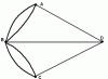
 Ampere's experience
Two parallel conductors, through which an electric current flows, interact with each other: they attract if the currents are in the same direction, and repel if the currents are in the opposite direction. This occurs due to the interaction of magnetic fields arising around the conductors.
Properties of magnetic field
1. Materially, i.e. exists independently of us and our knowledge about it.
2. Created by magnets, conductors with current (moving charged particles)
3. Detected by the interaction of magnets, conductors with current (moving charged particles)
4. Acts on magnets, current-carrying conductors (moving charged particles) with some force
5. None magnetic charges does not exist in nature. It is impossible to separate the northern and south poles and get a body with one pole.
6. The reason why bodies have magnetic properties was found by the French scientist Ampere. Ampere put forward the conclusion that the magnetic properties of any body are determined by closed electric currents inside it.
These currents represent the movement of electrons around orbits in an atom.
If the planes in which these currents circulate are located randomly in relation to each other due to the thermal movement of the molecules that make up the body, then their interactions are mutually compensated and the body does not exhibit any magnetic properties.
And vice versa: if the planes in which the electrons rotate are parallel to each other and the directions of the normals to these planes coincide, then such substances enhance the external magnetic field.
7. Magnetic forces act in a magnetic field in certain directions, which are called magnetic lines of force. With their help, you can conveniently and clearly show the magnetic field in a particular case.
 In order to more accurately depict the magnetic field, we agreed to show in those places where the field is stronger power lines located more densely, i.e. closer to each other. And vice versa, in places where the field is weaker, fewer field lines are shown, i.e. less frequently located.
8. The magnetic field is characterized by the magnetic induction vector.
Magnetic induction vector - vector quantity, characterizing the magnetic field.
The direction of the magnetic induction vector coincides with the direction of the north pole of the free magnetic needle at a given point.
The direction of the field induction vector and current strength I are related by the “right screw (gimlet) rule”:
 if you screw in a gimlet in the direction of the current in the conductor, then the direction of the speed of movement of the end of its handle at a given point will coincide with the direction of the magnetic induction vector at that point.
CONSTANT MAGNETIC FIELDS. Sources of permanent magnetic fields (PMF) in workplaces are permanent magnets, electromagnets, high-current systems DC(DC transmission lines, electrolyte baths and other electrical devices). Permanent magnets and electromagnets are widely used in instrument making, in magnetic washers of cranes and other fixing devices, in magnetic separators, devices for magnetic water treatment, magnetohydrodynamic generators (MHD), nuclear magnetic resonance (NMR) and electron paramagnetic resonance (EPR) installations. , as well as in physiotherapeutic practice.
Basic physical parameters, characterizing PMP:
2.0 T (short-term exposure to the body);
5.0 T (short-term exposure to hands);
for the population -
0.01 T (continuous exposure).
Control of PMP at workplaces is carried out in the order of preventive and routine sanitary supervision by measuring field strength and magnetic induction (magnetic flux density). Measurements are carried out at permanent workplaces where personnel may be located. If there is no permanent workplace within the working area, several points are selected, located at different distances from the source. When performing manual operations in the area covered by the PMF and when working with magnetized materials (powders) and permanent magnets, when contact with the PMF is limited to local influence (hands, shoulder girdle), measurements should be taken at the level of the final phalanges of the fingers, the middle of the forearm, the middle shoulder
Measurements of magnetic induction of permanent magnets are carried out by direct contact of the device sensor with the surface of the magnet. In hygienic practice, devices based on the laws of induction and the Hall effect are used. Fluxmeters (Webermeters) or ballistic galvanometers directly measure changes in magnetic flux, which is connected to a calibrated measuring coil; The most commonly used are ballistic galvanometers of the M-197/1 and M-197/2 types, fluxmeters of the M-119 and M-119t type, and Teslameters.
Oersted meters can be used to measure the intensity of the PMF according to the degree of deflection of the magnetized needle, i.e., according to the magnitude of the moment of forces turning the needle at a certain point in space.
Areas of the production area with levels exceeding the maximum permissible limit should be marked with special warning signs with an additional explanatory inscription “Caution! Magnetic field!". It is necessary to reduce the impact of PMF on workers by choosing a rational mode of work and rest, reducing the time spent in the conditions of PMF, and determining a route that limits contact with PMF in the work area.
Prevention of exposure to PMPs. When conducting repair work Busbar trunking systems should be provided with shunting. Persons servicing DC technological installations, busbar systems or in contact with PMP sources must undergo preliminary and periodic tests in the prescribed manner.
At electronics industry enterprises, when assembling semiconductor devices, end-to-end technological cassettes are used, which limit the contact of hands with the PMP. At enterprises producing permanent magnets, the process of measuring the magnetic parameters of products is automated using devices that exclude contact with the PMP. It is advisable to use remote devices (forceps made of non-magnetic materials, tweezers, grippers), which prevent the possibility of local action of PMP on the worker. Blocking devices must be used to turn off the electromagnetic installation when hands enter the PMP coverage area.
A magnet is a body that forms a magnetic field around itself.
The force created by a magnet will act on certain metals: iron, nickel and cobalt. Objects made of these metals are attracted by a magnet.
(the match and the cork do not attract, the nail only right half magnet, paper clip - to any place)
There are two areas where the force of attraction is maximum. They are called poles. If you hang a magnet on a thin thread, it will unfold in a certain way. One end will always point north and the other end south. Therefore, one pole is called the north, and the other - the south. 
You can clearly see the effect of the magnetic field formed around a magnet. Let's place the magnet on a surface on which metal filings have previously been poured. Under the influence of a magnetic field, the sawdust will be arranged in the form of ellipse-like curves. By the appearance of these curves, one can imagine how magnetic field lines are located in space. Their direction is usually designated from north to south. 
If we take two identical magnets and try to bring their poles closer together, we will find out that different poles attract, and similar ones repel. 
Our Earth also has a magnetic field called the Earth's magnetic field. The north end of the arrow always points north. Therefore, northern geographic pole The earth is southern magnetic pole because opposite magnetic poles attract. Likewise, the geographic south pole is the magnetic north pole. 
The north end of the compass needle always points north, as it is attracted by the Earth's south magnetic pole.
If we place a compass under a wire that is stretched in the direction from north to south and through which a current flows, we will see that the magnetic needle will deviate. This proves that electric current creates a magnetic field around itself. 
If we place several compasses under a wire through which an electric current flows, we will see that all the arrows will deviate by the same angle. This means that the magnetic field created by the wire is the same in different areas. Therefore, we can conclude that the magnetic field lines for each conductor have the form of concentric circles. 
The direction of magnetic field lines can be determined using the right-hand rule. To do this, you need to mentally clasp the conductor with electric current with your right hand so that the extended thumb of your right hand shows the direction of the electric current, then the bent fingers will show the direction of the magnetic field lines. 
If we twist a metal wire into a spiral and run an electric current through it, then the magnetic fields of each individual turn are summed up into the total field of the spiral. 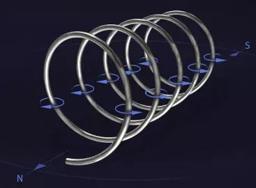
The action of the magnetic field of the spiral is similar to the action of the magnetic field of a permanent magnet. This principle formed the basis for the creation of an electromagnet. It, like a permanent magnet, has a south and north pole. The North Pole is where the magnetic field lines come from. 
The strength of a permanent magnet does not change over time. With an electromagnet it is different. There are three ways to change the strength of an electromagnet.
First way. Let's place a metal core inside the spiral. In this case, the actions of the magnetic field of the core and the magnetic field of the spiral are summed up.
Second way. Let's increase the number of turns of the spiral. The more turns the spiral has, the more action magnetic field strength.
Third way. Let's increase the strength of the electric current that flows in the spiral. Magnetic fields individual turns will increase, therefore, the total magnetic field of the spiral will also increase. 
Speaker
The loudspeaker device includes an electromagnet and a permanent magnet. The electromagnet, which is connected to the loudspeaker membrane, is placed on a rigidly fixed permanent magnet. At the same time, the membrane remains mobile. Let us pass an alternating electric current through an electromagnet, the type of which depends on sound vibrations. As the electric current changes, the effect of the magnetic field in the electromagnet changes.
As a result, the electromagnet will be attracted or repelled from the permanent magnet with different strength. Moreover, the loudspeaker membrane will perform exactly the same vibrations as the electromagnet. Thus, what was said into the microphone will be heard through the loudspeaker. 
Call
An electric doorbell can be classified as an electrical relay. The reason for the intermittent sound signal are periodic short circuits and openings of the electrical circuit.
When the bell button is pressed, the electrical circuit is closed. The bell tongue is attracted by an electromagnet and strikes the bell. In this case, the tongue opens the electrical circuit. The current stops flowing, the electromagnet does not act and the tongue returns to its original position. Electric circuit closes again, the tongue is again attracted by the electromagnet and strikes the bell. This process will continue as long as we press the call button. 
Electric motor
Let's install a freely rotating magnetic needle in front of the electromagnet and spin it. We can maintain this movement if we turn on the electromagnet at the moment when the magnetic needle turns the same pole towards the electromagnet.
The attractive force of the electromagnet is sufficient to rotational movement the arrows did not stop.  (in the picture, the magnet receives a pulse whenever the red arrow is near and the button is pressed. If you press the button when the green arrow is near, the electromagnet stops)
This principle is the basis of the electric motor. Only it is not a magnetic needle that rotates in it, but an electromagnet, called an armature, in a statically fixed horseshoe-shaped magnet, which is called a stator. Due to repeated closing and opening of the circuit, the electromagnet, i.e. the anchor will rotate continuously. 
Electric current enters the armature through two contacts, which are two insulated half rings. This causes the electromagnet to constantly change polarity. When opposite poles are opposite one another, the motor begins to slow down. But at this moment the electromagnet changes polarity, and now there are identical poles opposite each other. They push off and the motor continues to rotate. 
Generator
Let's connect a voltmeter to the ends of the spiral and begin to swing a permanent magnet in front of its turns. In this case, the voltmeter will show the presence of voltage. From this we can conclude that the electrical conductor is affected by a changing magnetic field.
From this follows the law of electrical induction: a voltage will exist at the ends of the induction coil as long as the coil is in a changing magnetic field.
The more turns an induction coil has, the more voltage appears at its ends. The voltage can be increased by making the magnetic field stronger or by causing it to change faster. A metal core inserted inside the induction coil increases the induction voltage as the magnetic field is enhanced due to the magnetization of the core.  (the magnet begins to be waved more strongly in front of the coil, as a result of which the voltmeter needle deflects much more)
A generator is the opposite of an electric motor. Anchor, i.e. An electromagnet rotates in the magnetic field of a permanent magnet. Due to the rotation of the armature, the magnetic field acting on it is constantly changing. As a result, the resulting induction voltage changes. During full turn The armature voltage will be positive half the time and negative half the time. An example of this is a wind generator that produces alternating voltage. 
Transformer
According to the law of induction, voltage occurs if the magnetic field changes in induction coil. But the magnetic field of the coil will change only if an alternating voltage appears in it.
The magnetic field changes from zero to a finite value. If you connect the coil to a voltage source, the resulting alternating magnetic field will create a short-term induction voltage that will counteract the main voltage. To observe the occurrence of induced voltage, it is not necessary to use two coils. This can be done with one coil, but then this process is called self-induction. The voltage in the coil reaches its maximum after some time, when the magnetic field stops changing and becomes constant. ![]()
The magnetic field changes in the same way if we disconnect the coil from the voltage source. In this case, the phenomenon of self-induction also occurs, which counteracts the falling voltage. Therefore, the voltage does not drop to zero instantly, but with a certain delay. ![]()
If we constantly connect and disconnect a voltage source to the coil, then the magnetic field around it will constantly change. At the same time, an alternating induction voltage also arises. Now, instead, let's connect the coil to an AC voltage source. After some time, an alternating induction voltage appears. ![]()
Let's connect the first coil to an alternating voltage source. Thanks to the metal core, the resulting alternating magnetic field will also act on the second coil. This means that alternating voltage can be transferred from one electric current circuit to another, even if these circuits are not connected to one another. ![]()
If we take two coils with identical parameters, then in the second we can get the same voltage that acts on the first coil. This phenomenon is used in transformers. Only the purpose of the transformer is to create a different voltage in the second coil, different from the first. To do this, the second coil must have a greater or lesser number of turns. ![]()
If the first coil had 1000 turns, and the second - 10, then the voltage in the second circuit will be only a hundredth of the voltage in the first. But the current strength increases almost a hundred times. Therefore transformers high voltage necessary to create great strength current ![]()