Construction of images in mirrors and their characteristics.
Image of any point A of an object in spherical mirror can be constructed using any pair of standard rays: To construct an image of any point A of an object, it is necessary to find the point of intersection of any two reflected rays or their extensions; the most convenient are rays running as shown in Figures 2.6 - 2.9
2) a ray passing through the focus, after reflection, will go parallel to the optical axis on which this focus lies;
4) the beam incident on the pole of the mirror, after reflection from the mirror, goes symmetrically to the main optical axis (AB=BM)
Let's look at a few examples of constructing images in concave mirrors:
2) The object is located at a distance that is equal to the radius of curvature of the mirror. The image is real, equal in size to the size of the object, inverted, located strictly under the object (Fig. 2.11).
 Rice. 2.12 Rice. 2.12 |
3) The object is located between the focus and the pole of the mirror. Image – virtual, enlarged, direct (Fig. 2.12)
Mirror formula
Let's find a connection between optical characteristics and distances that determine the position of the object and its image.
Let the object be a certain point A located on the optical axis. Using the laws of light reflection, we will construct an image of this point (Fig. 2.13).

Let us denote the distance from the object to the pole of the mirror (AO), and from the pole to the image (OA¢).
Consider the triangle APC, we find that
From triangle APA¢, we obtain that ![]() . Let us exclude the angle from these expressions, since it is the only one that does not rely on the OR.
. Let us exclude the angle from these expressions, since it is the only one that does not rely on the OR.
, ![]() or
or
![]() (2.3)
(2.3)
Angles b, q, g rest on OR. Let the beams under consideration be paraxial, then these angles are small and, therefore, their values in radian measure are equal to the tangent of these angles:
; ;  , where R=OC, is the radius of curvature of the mirror.
Let us substitute the resulting expressions into equation (2.3)


Since we previously found out that the focal length is related to the radius of curvature of the mirror, then
 (2.4)
(2.4)
Expression (2.4) is called the mirror formula, which is used only with the sign rule:
Distances , , are considered positive if they are measured along the path of the ray, and negative otherwise.
Convex mirror.
Let's look at several examples of constructing images in convex mirrors.
2) The object is located at a distance equal to the radius curvature. Imaginary image, reduced, direct (Fig. 2.15)
The focus of a convex mirror is imaginary. Convex mirror formula
![]() .
.
The sign rule for d and f remains the same as for a concave mirror.
The linear magnification of an object is determined by the ratio of the height of the image to the height of the object itself
![]() . (2.5)
. (2.5)
Thus, regardless of the location of the object relative to the convex mirror, the image always turns out to be virtual, straight, reduced and located behind the mirror. While the images in a concave mirror are more varied, they depend on the location of the object relative to the mirror. Therefore, concave mirrors are used more often.
Having examined the principles of constructing images in various mirrors, we have come to understand the operation of such various instruments as astronomical telescopes and magnifying mirrors in cosmetic devices and medical practice, we are able to design some devices ourselves.
If the reflecting surface of the mirror is flat, then it is a type of flat mirror. Light is always reflected from a flat mirror without scattering according to the laws of geometric optics:
- Angle of incidence equal to angle reflections.
- The incident ray, the reflected ray, and the normal to the mirror surface at the point of incidence lie in the same plane.
It should be remembered that a glass mirror has a reflective surface (usually thin layer aluminum or silver) is placed on its back side. They cover her protective layer. This means that although the main reflected image is formed on this surface, light will also be reflected from the front surface of the glass. A secondary image is formed, which is much weaker than the main one. It is usually invisible in everyday life, but creates serious problems in the field of astronomy. For this reason, all astronomical mirrors have a reflective surface applied to the front side of the glass.
Image Types
There are two types of images: real and imaginary.

The real is formed on the film of a video camera, camera or on the retina of the eye. Light rays pass through a lens or objective, converge when falling on a surface, and at their intersection form an image.
Imaginary (virtual) is obtained when rays, reflected from a surface, form a divergent system. If we complete the continuation of the rays in the opposite side, then they will definitely intersect at a certain (imaginary) point. It is from these points that a virtual image is formed, which cannot be recorded without the use of a flat mirror or other optical instruments (magnifying glass, microscope or binoculars).
Image in a plane mirror: properties and construction algorithm
For real object, the image obtained using a plane mirror is:
- imaginary;
- straight (not inverted);
- the dimensions of the image are equal to the dimensions of the object;
- the image is at the same distance behind the mirror as the object in front of it.
Let's construct an image of some object in flat mirror.

Let's use the properties of a virtual image in a plane mirror. Let's draw an image of a red arrow on the other side of the mirror. Distance A is equal to distance B, and the image is the same size as the object.

A virtual image is obtained at the intersection of the continuation of reflected rays. Let's depict light rays, going from the imaginary red arrow to the eye. Let us show that the rays are imaginary by drawing them with a dotted line. Continuous lines extending from the surface of the mirror show the path of the reflected rays.

Let's draw straight lines from the object to the points of reflection of the rays on the surface of the mirror. We take into account that the angle of incidence is equal to the angle of reflection.

Flat mirrors are used in many optical instruments. For example, in a periscope, flat telescope, graphic projector, sextant and kaleidoscope. A dental mirror for examining the oral cavity is also flat.
Construction of images in spherical mirrors
In order to construct an image of any point light source in a spherical mirror, it is enough to construct a path any two rays emanating from this source and reflected from the mirror. The intersection point of the reflected rays themselves will give a real image of the source, and the intersection point of the extensions of the reflected rays will give an imaginary one.
Characteristic rays. To construct images in spherical mirrors, it is convenient to use certain characteristic rays, the course of which is easy to construct.
1. Beam 1 , incident on the mirror parallel to the main optical axis, reflected, passes through the main focus of the mirror in a concave mirror (Fig. 3.6, A); in a convex mirror, a continuation of the reflected ray passes through the main focus 1 ¢ (Fig. 3.6, b).
2. Beam 2 , passing through the main focus of a concave mirror, having been reflected, goes parallel to the main optical axis - a ray 2 ¢ (Fig. 3.7, A). Beam 2 , incident on a convex mirror so that its continuation passes through the main focus of the mirror, having been reflected, it also goes parallel to the main optical axis - a ray 2 ¢ (Fig. 3.7, b).
Rice. 3.7 
3. Consider a ray 3 , passing through center concave mirror - point ABOUT(Fig. 3.8, A) and beam 3 , incident on a convex mirror so that its continuation passes through the center of the mirror - the point ABOUT(Fig. 3.8, b). As we know from geometry, the radius of a circle is perpendicular to the tangent to the circle at the point of contact, so the rays 3 in Fig. 3.8 fall on the mirrors under right angle, that is, the angles of incidence of these rays are zero. This means that the reflected rays 3 ¢ in both cases coincide with the falling ones.
Rice. 3.8 
4. Beam 4 , passing through pole mirrors - point R, is reflected symmetrically relative to the main optical axis (rays 4¢ in Fig. 3.9), since the angle of incidence is equal to the angle of reflection.
Rice. 3.9 
STOP! Decide for yourself: A2, A5.
Reader: Once I took an ordinary tablespoon and tried to see my image in it. I saw the image, but it turned out that if you look at convex part of a spoon, then the image direct, and if on concave, That inverted. I wonder why this is so? After all, a spoon, I think, can be considered as some kind of spherical mirror.
Task 3.1. Construct images of small vertical segments of the same length in a concave mirror (Fig. 3.10). The focal length is set. It is considered known that the images of small straight segments perpendicular to the main optical axis in a spherical mirror also represent small straight segments perpendicular to the main optical axis.

Solution.
1. Case a. Note that in this case all objects are in front of the main focus of the concave mirror.
 Rice. 3.11 Rice. 3.11 |
We will construct images only of the top points of our segments. To do this, draw through all the upper points: A, IN And WITH one common beam 1 , parallel to the main optical axis (Fig. 3.11). Reflected beam 1 F 1 .
Now from the points A, IN And WITH let's send out rays 2 , 3 And 4 through the main focus of the mirror. Reflected rays 2 ¢, 3 ¢ and 4 ¢ will go parallel to the main optical axis.
Points of intersection of rays 2 ¢, 3 ¢ and 4 ¢ with beam 1 ¢ are images of points A, IN And WITH. These are the points A¢, IN¢ and WITH¢ in fig. 3.11.
To get images segments it is enough to omit from the points A¢, IN¢ and WITH¢ perpendiculars to the main optical axis.
As can be seen from Fig. 3.11, all images turned out valid And upside down.
Reader: What do you mean – valid?
Author: The image of objects happens valid And imaginary. We already became acquainted with the virtual image when we studied a plane mirror: the virtual image of a point source is the point at which they intersect continuation rays reflected from the mirror. The actual image of a point source is the point at which the themselves rays reflected from the mirror.
Note that what further there was an object from the mirror, so smaller it turned out his image and that closer this is the image to mirror focus. Note also that the image of a segment whose lowest point coincided with center mirrors - dot ABOUT, it worked symmetrical object relative to the main optical axis.
I hope you now understand why, looking at your reflection in the concave surface of a tablespoon, you saw yourself reduced and inverted: after all, the object (your face) was clearly before the main focus of a concave mirror.
2. Case b. In this case, the objects are between the main focus and the surface of the mirror.
 The first ray is the ray 1
, as in the case A, let us pass through the upper points of the segments - points A And IN 1
¢ will pass through the main focus of the mirror - the point F 1 (Fig. 3.12).
The first ray is the ray 1
, as in the case A, let us pass through the upper points of the segments - points A And IN 1
¢ will pass through the main focus of the mirror - the point F 1 (Fig. 3.12).
Now let's use the rays 2 And 3 emanating from points A And IN and passing through pole mirrors - point R. Reflected rays 2 ¢ and 3 ¢ make the same angles with the main optical axis as the incident rays.
As can be seen from Fig. 3.12, reflected rays 2 ¢ and 3 ¢ do not intersect with reflected beam 1 ¢. Means, valid images in this case No. But continuation reflected rays 2 ¢ and 3 ¢ intersect with continuation reflected beam 1 ¢ at points A¢ and IN¢ behind the mirror, forming imaginary dot images A And IN.
Dropping perpendiculars from points A¢ and IN¢ to the main optical axis, we obtain images of our segments.
As can be seen from Fig. 3.12, the images of the segments turned out straight And enlarged, and what closer subject to the main focus, the more his image and theme further This is the image from the mirror.
STOP! Decide for yourself: A3, A4.
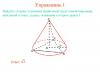
Problem 3.2. Construct images of two small identical vertical segments in a convex mirror (Fig. 3.13).
 |  |
Rice. 3.13 Fig. 3.14
Solution. Let's send out a beam 1 through the upper points of the segments A And IN parallel to the main optical axis. Reflected beam 1 ¢ will go so that its continuation intersects the main focus of the mirror - the point F 2 (Fig. 3.14).
Now let's send rays onto the mirror 2 And 3 from points A And IN so that the continuations of these rays pass through center mirrors - point ABOUT. These rays will be reflected so that the reflected rays 2 ¢ and 3 ¢ coincide with the incident rays.
As we see from Fig. 3.14, reflected beam 1 ¢ does not intersect with reflected rays 2 ¢ and 3 ¢. Means, valid dot images A And B no. But continuation reflected beam 1 ¢ intersects with continuations reflected rays 2 ¢ and 3 ¢ at points A¢ and IN¢. Therefore, the points A¢ and IN¢ – imaginary dot images A And IN.
To build images segments drop the perpendiculars from the points A¢ and IN¢ to the main optical axis. As can be seen from Fig. 3.14, the images of the segments turned out straight And reduced. And what? closer the object to the mirror, the more his image and theme closer it's towards the mirror. However, even a very distant object cannot produce an image distant from the mirror beyond the main focus of the mirror.
I hope it is now clear why, when looking at your reflection in the convex surface of the spoon, you saw yourself reduced, but not inverted.
STOP! Decide for yourself: A6.
When constructing an image of any source point, there is no need to consider many rays. To do this, it is enough to build two beams; the point where they intersect will determine the location of the image. It is most convenient to construct those rays whose course is easy to trace. The path of these rays in the case of reflection from a mirror is shown in Fig. 213.
Rice. 213. Various techniques constructing an image in a concave spherical mirror
Ray 1 passes through the center of the mirror and is therefore normal to the surface of the mirror. This beam returns after reflection exactly back along the secondary or main optical axis.
Beam 2 is parallel to the main optical axis of the mirror. This ray, after reflection, passes through the focus of the mirror.
Ray 3, which from the object point passes through the focus of the mirror. After reflection from the mirror, it goes parallel to the main optical axis.
Beam 4 incident on the mirror at its pole will be reflected back symmetrically with respect to the main optical axis. To construct an image, you can use any pair of these rays.
By constructing images of a sufficient number of points of an extended object, one can get an idea of the position of the image of the entire object. In the case of a simple object shape shown in Fig. 213 (a straight line segment perpendicular to the main axis), it is enough to construct just one image point. Slightly more complex cases are discussed in the exercises.
In Fig. 210 were given geometric constructions images for different positions of the object in front of the mirror. Rice. 210, c - the object is placed between the mirror and the focus - illustrates the construction of a virtual image using the continuation of rays behind the mirror.

Rice. 214. Constructing an image in a convex spherical mirror.
In Fig. 214 gives an example of constructing an image in a convex mirror. As stated earlier, in this case virtual images are always obtained.
To construct an image in a lens of any point on an object, just as when constructing an image in a mirror, it is enough to find the intersection point of any two rays emanating from this point. The simplest construction is performed using the rays shown in Fig. 215.

Rice. 215. Various techniques for constructing an image in a lens
Beam 1 goes along the secondary optical axis without changing direction.
Beam 2 falls on the lens parallel to the main optical axis; when refracted, this ray passes through the back focus.
Beam 3 passes through the front focus; When refracted, this ray travels parallel to the main optical axis.
The construction of these rays is carried out without any difficulty. Any other ray coming from the point would be much more difficult to construct - one would have to directly use the law of refraction. But this is not necessary, since after the construction is completed, any refracted ray will pass through the point.
It should be noted that when solving the problem of constructing an image of off-axis points, it is not at all necessary that the selected simplest pairs of rays actually pass through the lens (or mirror). In many cases, for example when photographing, the object is much larger than the lens, and rays 2 and 3 (Fig. 216) do not pass through the lens. However, these rays can be used to construct an image. Real beam and, participating in the formation of the image, are limited by the frame of the lens (shaded cones), but converge, of course, at the same point, since it has been proven that when refracted in a lens, the image of a point source is again a point.

Rice. 216. Constructing an image in the case when the object is significantly larger than the lens
Let's consider several typical cases of image in a lens. We will consider the lens to be converging.
1. The object is located from the lens at a distance greater than twice the focal length. This is usually the position of the subject when photographing.

Rice. 217. Constructing an image in a lens when the object is located beyond double focal length
The construction of the image is shown in Fig. 217. Since , then according to the lens formula (89.6)
![]() ,
,
i.e. the image lies between the back focus and the thin one located on the double focal length from the optical center of the lens. The image is inverted (reverse) and reduced, since according to the magnification formula
2. Let's note something important special case when a beam of rays parallel to some secondary optical axis falls on the lens. Similar case occurs, for example, when photographing very distant extended objects. The construction of the image is shown in Fig. 218.
In this case, the image lies on the corresponding secondary optical axis, at the point of its intersection with the rear focal plane (the so-called plane perpendicular to main axis and passing through the back focus of the lens).

Rice. 218. Constructing an image in the case when a beam of rays parallel to the secondary optical axis falls on the lens
Points of the focal plane are often called the foci of the corresponding secondary axes, reserving the name main focus for the point corresponding to the main axis.
The focal distance from the main optical axis of the lens and the angle between the secondary axis in question and main axis are obviously connected by the formula (Fig. 218)
3. The object lies between the point at twice the focal length and the front focus - the usual position of the object when projecting with a projection lamp. To study this case, it is enough to use the property of image reversibility in a lens. We will consider it a source (see Fig. 217), then it will be an image. It is easy to see that in the case under consideration the image is reversed, enlarged and lies from the lens at a distance greater than double the focal length.
It is useful to note the special case when the object is located from the lens at a distance equal to double the focal length, i.e. Then according to the lens formula
![]() ,
,
that is, the image lies from the lens also at double the focal length. The image in this case is inverted. To increase we find
that is, the image has the same dimensions as the object.
4. Of great importance is the special case when the source is in a plane perpendicular to the main axis of the lens and passing through the front focus.
This plane is also the focal plane; it is called the front focal plane. If the point source is located at any of the points of the focal plane, i.e., at one of the front foci, then a parallel beam of rays emerges from the lens, directed along the corresponding optical axis (Fig. 219). The angle between this axis and the main axis and the distance from the source to the axis are related by the formula
5. The object lies between the front focus and the lens, i.e. In this case, the image is direct and virtual.
The construction of the image in this case is shown in Fig. 220. Since , then to increase we have
i.e. the image is enlarged. We'll be back to this case when viewing with a magnifying glass.

Rice. 219. The sources and lie in the front focal plane. (Beams of rays emerge from the lens, parallel to the side axes passing through the source points)

Rice. 220. Constructing an image when an object lies between the front focus and the lens
6. Constructing an image for a diverging lens (Fig. 221).
The image in a diverging lens is always virtual and direct. Finally, since , the image is always reduced.

Rice. 221. Constructing an image in a diverging lens
Note that with all constructions of rays passing through a thin lens, we may not consider their path inside the lens itself. It is only important to know the location of the optical center and main focal points. Thus, a thin lens can be represented by a plane passing through optical center perpendicular to the main optical axis, on which the positions of the main foci should be marked. This plane is called the principal plane. It is obvious that the ray entering and exiting the lens passes through the same point on the main plane (Fig. 222, a). If we save the outlines of a lens in the drawings, then only for the visual distinction of a converging and diverging lens; for all constructions these outlines are unnecessary. Sometimes, to make the drawing simpler, lenses are used instead of outlines. symbolic image, shown in Fig. 222, b.

Rice. 222. a) Replacing the lens with the main plane; b) symbolic image of a converging (left) and diverging (right) lens; c) replacing the mirror with the main plane
Similarly, a spherical mirror can be represented by a principal plane that touches the surface of the sphere at the pole of the mirror, indicating on the principal axis the position of the center of the sphere and the principal focus. The position indicates whether we are dealing with a concave (collecting) or convex (scattering) mirror (Fig. 222, c).