Let us find the connection between the optical characteristic and the distances that determine the position of the object and its image.
Let the object be a certain point A located on the optical axis. Using the laws of light reflection, we will construct an image of this point (Fig. 2.13).
Let us denote the distance from the object to the pole of the mirror  (AO), and from pole to image
  (OA).
(OA).
Consider the triangle APC, we find that 
From the triangle APA, we obtain that  . Let us exclude the angle from these expressions
  , since it is the only one that does not rely on OR.
 ,
,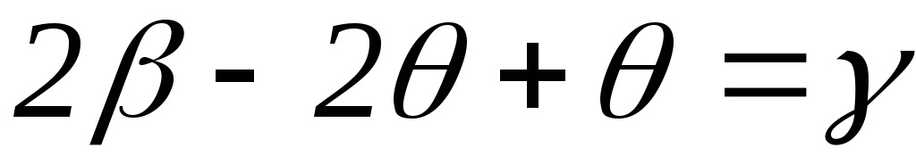 or
or
 (2.3)
(2.3)
Angles ,,are based on OR. Let the beams under consideration be paraxial, then these angles are small and, therefore, their values in radian measure are equal to the tangent of these angles:
 ;
;
 ;
; , where R=OC, is the radius of curvature of the mirror.
Let us substitute the resulting expressions into equation (2.3)


Since we previously found out that the focal length is related to the radius of curvature of the mirror, then
 (2.4)
(2.4)
Expression (2.4) is called the mirror formula, which is used only with the sign rule:
Distances  ,
, ,
, are considered positive if they are counted along the ray, and negative otherwise.
Convex mirror.
Let's look at several examples of constructing images in convex mirrors.


The focus of a convex mirror is imaginary. Convex mirror formula
 .
.
The sign rule for d and f remains the same as for a concave mirror.
The linear magnification of an object is determined by the ratio of the height of the image to the height of the object itself
 . (2.5)
Thus, regardless of the location of the object relative to the convex mirror, the image always turns out to be virtual, straight, reduced and located behind the mirror. While the images in a concave mirror are more varied, they depend on the location of the object relative to the mirror. Therefore, concave mirrors are used more often.
Having considered the principles of constructing images in various mirrors, we have come to understand the operation of such various instruments as astronomical telescopes and magnifying mirrors in cosmetic devices and medical practice, we are able to design some devices ourselves.
mirror image, diffuse reflection
Flat mirror.
The simplest optical system is a flat mirror. If a parallel beam of rays incident on a flat surface between two media remains parallel after reflection, then the reflection is called mirror, and the surface itself is called a plane mirror (Fig. 2.16).


If the reflecting surface is rough, then the reflection wrong and the light scatters, or diffusely reflected (Fig. 2.19)

Diffuse reflection is much more pleasing to the eye than reflection from smooth surfaces, called correct reflection.
Lenses.
Lenses, like mirrors, are optical systems, i.e. capable of changing course light beam. Lenses can be different in shape: spherical, cylindrical. We will focus only on spherical lenses.

A transparent body bounded by two spherical surfaces is called lens.

Converging lenses . Focus A converging lens is the point at which rays parallel to the optical axis intersect after refraction in the lens. The focus of the converging lens is real. The focus lying on the main optical axis is called the main focus. Any lens has two main focuses: the front (from the side of the incident rays) and the back (from the side of the refracted rays). The plane in which the foci lie is called the focal plane. The focal plane is always perpendicular to the main optical axis and passes through the main focus. The distance from the center of the lens to the main focus is called the main focal length F (Fig. 2.21).

To construct images of any luminous point, one should trace the course of any two rays incident on the lens and refracted in it until they intersect (or intersect their continuation). The image of extended luminous objects is a collection of images of its individual points. The most convenient rays used in constructing images in lenses are the following characteristic rays:


Figure 2.25 demonstrates the construction of an image of point A of object AB.

In addition to the listed rays, when constructing images in thin lenses, rays parallel to any secondary optical axis are used. It should be borne in mind that rays incident on a collecting lens in a beam parallel to the secondary optical axis intersect the rear focal surface at the same point as the secondary axis.
Thin lens formula:
 , (2.6)
where F - focal length lenses; D is the optical power of the lens; d is the distance from the object to the center of the lens; f is the distance from the center of the lens to the image. The sign rule will be the same as for a mirror: all distances to real points are considered positive, all distances to imaginary points are considered negative.
The linear magnification given by the lens is
 , (2.7)
where H is the image height; h is the height of the object.
Diffusing Lenses . Rays incident on a diverging lens in a parallel beam diverge so that their extensions intersect at a point called imaginary focus.
Rules for the path of rays in a diverging lens:

2) the beam traveling along the optical axis does not change its direction.
Diverging lens formula:

(the rule of signs remains the same).
Figure 2.27 shows an example of imaging in diverging lenses.
When constructing an image of any source point, there is no need to consider many rays. To do this, it is enough to build two beams; the point where they intersect will determine the location of the image. It is most convenient to construct those rays whose course is easy to trace. The path of these rays in the case of reflection from a mirror is shown in Fig. 213.
Rice. 213. Various techniques constructing an image in a concave spherical mirror
Ray 1 passes through the center of the mirror and is therefore normal to the surface of the mirror. This beam returns after reflection exactly back along the secondary or main optical axis.
Beam 2 is parallel to the main optical axis of the mirror. This ray, after reflection, passes through the focus of the mirror.
Ray 3, which from the object point passes through the focus of the mirror. After reflection from the mirror, it goes parallel to the main optical axis.
Beam 4 incident on the mirror at its pole will be reflected back symmetrically with respect to the main optical axis. To construct an image, you can use any pair of these rays.
By constructing images of a sufficient number of points of an extended object, one can get an idea of the position of the image of the entire object. In the case of a simple object shape shown in Fig. 213 (a straight line segment perpendicular to the main axis), it is enough to construct just one image point. Slightly more complex cases are discussed in the exercises.
In Fig. 210 were given geometric constructions images for different positions of the object in front of the mirror. Rice. 210, c - the object is placed between the mirror and the focus - illustrates the construction of a virtual image using the continuation of rays behind the mirror.

Rice. 214. Constructing an image in a convex spherical mirror.
In Fig. 214 gives an example of constructing an image in a convex mirror. As stated earlier, in this case virtual images are always obtained.
To construct an image in a lens of any point of an object, just as when constructing an image in a mirror, it is enough to find the intersection point of any two rays emanating from this point. The simplest construction is performed using the rays shown in Fig. 215.

Rice. 215. Various techniques for constructing an image in a lens
Beam 1 goes along the secondary optical axis without changing direction.
Beam 2 falls on the lens parallel to the main optical axis; when refracted, this ray passes through the back focus.
Beam 3 passes through the front focus; When refracted, this ray travels parallel to the main optical axis.
The construction of these rays is carried out without any difficulty. Any other ray coming from the point would be much more difficult to construct - one would have to directly use the law of refraction. But this is not necessary, since after the construction is completed, any refracted ray will pass through the point.
It should be noted that when solving the problem of constructing an image of off-axis points, it is not at all necessary that the selected simplest pairs of rays actually pass through the lens (or mirror). In many cases, for example when photographing, the object is much larger than the lens, and rays 2 and 3 (Fig. 216) do not pass through the lens. However, these rays can be used to construct an image. Real beam and, participating in the formation of the image, are limited by the frame of the lens (shaded cones), but converge, of course, at the same point, since it has been proven that when refracted in a lens, the image of a point source is again a point.

Rice. 216. Constructing an image in the case when the object is significantly larger than the lens
Let's consider several typical cases of image in a lens. We will consider the lens to be converging.
1. The object is located from the lens at a distance greater than twice the focal length. This is usually the position of the subject when photographing.

Rice. 217. Constructing an image in a lens when the object is located beyond double focal length
The construction of the image is shown in Fig. 217. Since , then according to the lens formula (89.6)
![]() ,
,
that is, the image lies between the back focus and a thin lens located at twice the focal length from the optical center. The image is inverted (reverse) and reduced, since according to the magnification formula
2. Let's note something important special case when a beam of rays parallel to some secondary optical axis falls on the lens. Similar case occurs, for example, when photographing very distant extended objects. The construction of the image is shown in Fig. 218.
In this case, the image lies on the corresponding secondary optical axis, at the point of its intersection with the rear focal plane (the so-called plane perpendicular to main axis and passing through the back focus of the lens).

Rice. 218. Constructing an image in the case when a beam of rays parallel to the secondary optical axis falls on the lens
Points of the focal plane are often called the foci of the corresponding secondary axes, reserving the name main focus for the point corresponding to the main axis.
The focal distance from the main optical axis of the lens and the angle between the secondary axis in question and main axis are obviously connected by the formula (Fig. 218)
3. The object lies between the point at twice the focal length and the front focus - the usual position of the object when projecting with a projection lamp. To study this case, it is enough to use the property of image reversibility in a lens. We will consider it a source (see Fig. 217), then it will be an image. It is easy to see that in the case under consideration the image is reversed, enlarged and lies from the lens at a distance greater than double the focal length.
It is useful to note the special case when the object is located from the lens at a distance equal to double the focal length, i.e. Then according to the lens formula
![]() ,
,
that is, the image lies from the lens also at double the focal length. The image in this case is inverted. To increase we find
that is, the image has the same dimensions as the object.
4. Of great importance is the special case when the source is in a plane perpendicular to the main axis of the lens and passing through the front focus.
This plane is also the focal plane; it is called the front focal plane. If the point source is located at any of the points of the focal plane, i.e., at one of the front foci, then a parallel beam of rays emerges from the lens, directed along the corresponding optical axis (Fig. 219). The angle between this axis and the main axis and the distance from the source to the axis are related by the formula
5. The object lies between the front focus and the lens, i.e. In this case, the image is direct and virtual.
The construction of the image in this case is shown in Fig. 220. Since , then to increase we have
i.e. the image is enlarged. We'll be back to this case when examining a magnifying glass.

Rice. 219. The sources and lie in the front focal plane. (Beams of rays emerge from the lens, parallel to the side axes passing through the source points)

Rice. 220. Constructing an image when an object lies between the front focus and the lens
6. Constructing an image for a diverging lens (Fig. 221).
The image in a diverging lens is always virtual and direct. Finally, since , the image is always reduced.

Rice. 221. Constructing an image in a diverging lens
Note that with all constructions of rays passing through a thin lens, we may not consider their path inside the lens itself. It is only important to know the location of the optical center and main focal points. Thus, a thin lens can be represented by a plane passing through the optical center perpendicular to the main optical axis, on which the positions of the main foci should be marked. This plane is called the principal plane. It is obvious that the ray entering and exiting the lens passes through the same point on the main plane (Fig. 222, a). If we save the outlines of a lens in the drawings, then only for the visual distinction of a converging and diverging lens; for all constructions these outlines are unnecessary. Sometimes, to make the drawing simpler, lenses are used instead of outlines. symbolic image, shown in Fig. 222, b.

Rice. 222. a) Replacing the lens with the main plane; b) symbolic image of a converging (left) and diverging (right) lens; c) replacing the mirror with the main plane
Similarly, a spherical mirror can be represented by a principal plane that touches the surface of the sphere at the pole of the mirror, indicating on the principal axis the position of the center of the sphere and the principal focus. The position indicates whether we are dealing with a concave (collecting) or convex (scattering) mirror (Fig. 222, c).
Construction of images in mirrors and their characteristics.
An image of any point A of an object in a spherical mirror can be constructed using any pair of standard rays: To construct an image of any point A of an object, it is necessary to find the point of intersection of any two reflected rays or their extensions; the most convenient are rays going as shown in the figures 2.6 – 2.9
2) a ray passing through the focus, after reflection, will go parallel to the optical axis on which this focus lies;
4) the beam incident on the pole of the mirror, after reflection from the mirror, goes symmetrically to the main optical axis (AB=BM)
Let's look at a few examples of constructing images in concave mirrors:
2) The object is located at a distance that is equal to the radius of curvature of the mirror. The image is real, equal in size to the size of the object, inverted, located strictly under the object (Fig. 2.11).
 Rice. 2.12 Rice. 2.12 |
3) The object is located between the focus and the pole of the mirror. Image – virtual, enlarged, direct (Fig. 2.12)
Mirror formula
Let's find a connection between optical characteristics and distances that determine the position of the object and its image.
Let the object be a certain point A located on the optical axis. Using the laws of light reflection, we will construct an image of this point (Fig. 2.13).

Let us denote the distance from the object to the pole of the mirror (AO), and from the pole to the image (OA¢).
Consider the triangle APC, we find that
From triangle APA¢, we obtain that ![]() . Let us exclude the angle from these expressions, since it is the only one that does not rely on the OR.
. Let us exclude the angle from these expressions, since it is the only one that does not rely on the OR.
, ![]() or
or
![]() (2.3)
(2.3)
Angles b, q, g rest on OR. Let the beams under consideration be paraxial, then these angles are small and, therefore, their values in radian measure are equal to the tangent of these angles:
; ;  , where R=OC, is the radius of curvature of the mirror.
Let us substitute the resulting expressions into equation (2.3)


Since we previously found out that the focal length is related to the radius of curvature of the mirror, then
 (2.4)
(2.4)
Expression (2.4) is called the mirror formula, which is used only with the sign rule:
Distances , , are considered positive if they are measured along the path of the ray, and negative otherwise.
Convex mirror.
Let's look at several examples of constructing images in convex mirrors.
2) The object is located at a distance equal to the radius of curvature. Imaginary image, reduced, direct (Fig. 2.15)
The focus of a convex mirror is imaginary. Convex mirror formula
![]() .
.
The sign rule for d and f remains the same as for a concave mirror.
The linear magnification of an object is determined by the ratio of the height of the image to the height of the object itself
![]() . (2.5)
. (2.5)
Thus, regardless of the location of the object relative to the convex mirror, the image always turns out to be virtual, straight, reduced and located behind the mirror. While the images in a concave mirror are more varied, they depend on the location of the object relative to the mirror. Therefore, concave mirrors are used more often.
Having examined the principles of constructing images in various mirrors, we have come to understand the operation of such various instruments as astronomical telescopes and magnifying mirrors in cosmetic devices and medical practice, we are able to design some devices ourselves.
Open lesson. Physics
Teacher: Lakizo I.A.
Lesson topic: Mirrors. Constructing images in a plane mirror
Purpose of the lesson: get acquainted with the concept of “flat mirror”; with an algorithm for constructing an image in a flat mirror; with the properties of the image of an object in a flat mirror; using flat mirrors in everyday life and technology.
Tasks:
- educational:
form the concepts of a plane mirror and an image in a plane mirror, the concept of an imaginary image; study methods for constructing images in a plane mirror at different relative positions of the object and the mirror; teach to establish relationships in the phenomena being studied; develop practical skills in building
- developing:
develop the ability to draw conclusions and generalizations, develop the eye, the ability to navigate in space and time, develop the ability to apply knowledge in specific situations, include children in the permission of educational problem situations, develop logical thinking; develop and maintain students’ attention through changing educational activities
- educational:
bring up cognitive interest, positive motivation for learning, accuracy in completing tasks .
Lesson type: combined
Forms of student work: oral decision practical problems, practical work with a mirror, abstract, creative work students (student messages “From the history of mirrors” and "The History of Kaleidoscope")
Learning Tools: Mirror, ruler, eraser, multimedia projector, computer, presentation
Lesson progress:
1. Updating basic knowledge.
Organizational moment
Types of survey:
1. Computer test(4 people)
2. Frontal survey
3. General survey (1 person)
4. Work at the board: formation (1 person at the board)
Frontal survey:
1. Optics is...
2. Light sources -…..
3. Light sources are...
4. Light beam-...
5. Point source-…
6. Reflection of light is...
7. Almost all surfaces reflect light. What types of reflections are there? What do these two types of reflection have in common?
8. Think and tell me, thanks to what reflection do we see the surrounding bodies?
9. Name the main rays and lines used for graphic image reflections of light.
10. Formulate the laws of light reflection.
11. On a clear sunny winter day, trees provide clear shadows on the snow, but on a cloudy day there are no shadows. Why?
7. Tasks. (We decide orally)
a) The angle of incidence is 30 degrees. Why equal to the angle reflections?
b) The angle of incidence of the beam is 15 degrees. What is the angle between the incident and reflected rays?
c) The angle of incidence was increased by 10 degrees. How did the angle between the incident and reflected rays change?
d) The angle between the incident and reflected rays is 90 degrees.
At what angle toDoes light fall on the mirror?
D) Light falls on the interface between two media perpendicularly. What are the angle of incidence and angle of reflection of light?
9. Determine which picture (1 or 2) shows diffuse reflection and which shows mirror image.
Summary survey: one student at the blackboard answers questions from classmates. A mark is set.
Work at the board:
- The correctness of the construction of the shadow and penumbra is checked.
- Checking the correctness of the crossword puzzle
Questions for the crossword:
1) a celestial object falling into the shadow of another object
2) a region of space where light does not fall from a light source
3) a phenomenon with the help of which we can see objects that themselves do not glow
4) scientist, founder of geometry, who wrote about linear propagation Sveta
5) science (section of physics) about the nature and properties of light
6) the line along which energy from the light source spreads
7) a property of rays in which the incident and reflected ray can change places
2. Learning new material
Which keyword did we get? Mirror.
Yes, topic of the lesson: Mirror. Constructing an image in a plane mirror. Write down the date and topic of the lesson in a notebook.
Today we should get acquainted with:
1. the concept of “flat mirror”;
2. with an algorithm for constructing an image in a flat mirror;
3. with the properties of the image of an object in a flat mirror;
4. using flat mirrors in everyday life and technology
Students are presented with three mirrors: with a flat surface, with a convex surface and a concave surface. Question: how are these mirrors different? We form the concept of what kind of mirrors there are
Today we will talk in more detail about flat mirrors.
Let's talk about the history of the creation of the mirror. Let's hear the message.
The history of the creation of mirrors.
The first mention of mirrors dates back to 1200 BC. e. 150 years ago, archaeologists discovered in one of Egyptian tombs a small metal disk covered with a thick layer of rust. The disk was mounted on the head of a figurine of a young woman. There was no guessing about his purpose. When a thick layer of black deposits was removed with sandpaper in the laboratory, a smooth polished surface came to light, in which the chemist saw his reflection. Mysterious item turned out to be a mirror. After examination, it turned out that the disk was made of bronze.
A bronze mirror quickly darkens from moisture, so in ancient times they tried to make silver mirrors. But silver also darkens over time. They did it in Rus' steel mirrors and called them “damask steel”. But they quickly darkened and became covered with a layer of rust.
Therefore, the question arose about how to protect the metal from exposure external environment: cover with something transparent.
Glass was first produced in the 15th century on the Italian island of Murano, not far from Venice. Murano masters were the first to learn how to make transparent glass. They found a way to make a flat sheet from a glass bubble. Now the question arose of how to combine metal and glass: after all, glass is very fragile. To prevent the glass from cracking, a very thin film of liquid metal must be applied to it. This difficult task allowed. A sheet of tin was spread on a smooth sheet of marble and mercury was poured over it. Tin dissolved in mercury. This solution was called amalgam. A sheet of glass was placed on it, and a silvery, shiny film of amalgam as thick as tissue paper adhered tightly to the glass. This is how the first real mirror was made.
Glass was very expensive at that time. To buy a small mirror, for example, in France, Countess de Fiesque sold her estate. Therefore, the Venetians very strictly guarded the secret of making a mirror. But in the 17th century French minister Colbert, under Louis XIV, was able to bribe three craftsmen from Murano and secretly transport them to France. The French turned out to be capable students and soon surpassed their teachers. At Versailles, they even built a 73-meter-long gallery of large mirrors, which made a stunning impression on the guests of the French king.
Now let's look at the mirror from a physics point of view.
Flat mirror – a specularly reflective surface if the beam incident on it parallel rays remains parallel.
What kind of image is obtained in a flat mirror? We will find out this experimentally.
Let's fill out the table (printed for each student, the blue color is the blanks - students fill in):
From a fairy tale by A. S. Pushkin
“My light, mirror, tell me
Tell me the whole truth,
Am I the sweetest in the world,
all blush and whiter..."
Does a flat mirror always tell the truth?
Let's conduct an experiment:
Let's conduct an experiment with a candle and glass. Let's place a lit candle in front of the glass. We observe the reflection of a candle. Now let's take an unlit candle and move it to the other side until the candle “lights up.”
Now let's measure:
- the distance to a given candle (distance to reflection) and is comparable to the distance to a lit candle (distance to an object). What can be concluded? The distance from the object to the mirror is equal to the distance from the mirror to the reflection.
- Let's measure the candle and the reflection. The dimensions of the object and the reflection are equal.
- There is a Japanese saying: “The flower in the mirror is good, but you won’t take it.” Is it correct from a physics point of view?
We have a piece of paper. How can you prove that reflection – imaginary? (We bring it to the display - it doesn’t light up).
Conclusion: a flat mirror gives an image equal in size, at the same distance, but symmetrical.
Attention to the screen. (fragment from the film “Well, wait a minute!” / Episode 2, Time: 6-00-7-00 /
Why did the hare and the wolf see distorted images in the mirrors?
Answer: Concave and convex mirrors are used in the laughter room.
Let's conduct a physical experiment(we invite two students).
Study of the properties of concave and convex mirrors.
Equipment and materials: concave and convex mirrors (metal spoons polished to a shine).
Work progress
1. The spoon has two sides - convex and concave. Hold the spoon (mirror) vertically in front of you and look at the convex part of the spoon. What does your image look like? Do you see yourself upright or upside down? Is the reflection stretched or not?
2. Turn the spoon horizontally. How did the image change?
3. Again, take the spoon (mirror) vertically, turn it over so that you look at the concave side of the spoon. What does your image look like now? Is it upside down? Have your features changed?
4. Turn the spoon horizontally. How did the image change?
5. Slowly bring the spoon (mirror) to your eyes. Has the image turned upside down, or is everything still the same?
Draw a conclusion.
Practical tasks
- 1. Construct an image in a plane mirror.
Method 1
1) Draw a perpendicular from point A to the surface of the mirror and continue it. O is the point of intersection of the perpendicular and the surface of the mirror.
2) From point O we set aside the distance OA 1, equal to distance OA (based on property 1).
3) Similarly, we will construct an image of point B 1.

Method 2
Let's construct an image of an object in a flat mirror using the law of light reflection. You all know very well that the image of an object in a mirror is formed behind the mirror, where it actually does not exist.
How does this work? ( The teacher presents the theory, students take an active part, one works at the blackboard)
- How many images can be obtained in two plane mirrors?, located at an angle to each other.
There is a formula by which you can calculate the number of images obtained from two mirrors located at different angles to each other:
n is the number of images, is the angle between the mirrors.
Using this formula, we determine:
at =90 0 n=3
at =45 0 n=7
at =30 0 n=11
Let's check this experimentally.
Practical Application: for trade advertising, in a window between mirrors located at an angle to each other, for example, one bottle of perfume is placed, but the impression of many such bottles is created. One bouquet of flowers placed in a vase among these mirrors creates the illusion of an entire field of flowers.
If you put mirrors parallel to each other and place a lit candle between them, then through the hole in the amalgam you can observe a whole corridor with candles.
Multiple reflection from mirrors is used in kaleidoscope, which was invented in England in 1816. Three mirrors form the surface of the prism. Colored pieces of glass are placed between them. By turning the kaleidoscope, you can observe thousands of beautiful paintings.
Focus "Severed Head". A mirror is placed between the legs of the table so that the audience is not reflected in it, and the walls and floor are the same color throughout the room.
"Use of Mirrors"
- 1. In everyday life.
The first mirrors were created to monitor one's own appearance.
Nowadays, mirrors, especially large ones, are widely used in interior design to create the illusion of space, large volume in small spaces. This idea arose in France in the 17th century during the reign of Louis XIV, the “Sun King”.
2. As reflectors Parabolic mirrors are used to create a beam of parallel rays (headlights, spotlights).
3. Scientific instruments: telescopes, lasers, SLR cameras
4. Safety devices, car and road mirrors
- mirror on the road at a sharp turn
- in cases where visibility is limited, slightly convex mirrors are used to expand the field of view (in every car, bus).
- On roads and in tight parking lots, stationary convex mirrors help avoid collisions and accidents.
- in video surveillance systems, mirrors provide visibility in more directions from one video camera.
5. In medicine:
-gastroscope(medical periscope) allows you to examine the stomach: identify ulcers, tumors, etc.
Mirrors at the dentist
6. Military affairs:
Military periscope;
Periscope on a submarine
- V thermonuclear weapons to focus radiation from the fuse and create conditions for the start of the thermonuclear fusion process.
Consolidation.
1. Answer the questions :
Three points located on the same straight line are reflected in a plane mirror. Will the images of these points be located on the same line and why does symmetry relative to a line preserve the parallelism of lines).
Does your image exist in the mirror if you do not see yourself in the mirror? If yes, how can you be sure of this? (other person can see your image)
A person approaches a mirror at a speed of 0.5 m/s.
a) At what speed is he approaching his image?
b) At what speed does the image approach the mirror?
2. Work on the test (printed on the desk)
Topic: Flat mirror
|
A flat mirror is |
||||
|
||||
|
What is the image of the luminous point and where is it formed in a plane mirror? |
||||
|
||||
|
The picture shows the imagesS' pointsS in a plane mirror. Which one was wrong? |
||||
|
|
|||
|
The figure shows images of objects (arrows) in a flat mirror. Which one shows the image correctly? |
||||
|
|
|||
|
The characteristics of the image of an object in a plane mirror are as follows: it... |
||||
|
||||
|
What properties of the image in a plane mirror distinguish it from the object itself? |
||||
|
||||
|
Back in ancient Greece Polished metal plates were used as mirrors, but the image quality in them was unimportant. Why? |
||||
|
||||


|
From what surface does reflection occur in an ordinary glass mirror? |
||||
|
||||
|
How many mirrors are used in a periscope? |
||||
|
||||
|
Light is reflected well from both the mirror and the freshly fallen snow. What's the difference? |
||||
|
||||


Let's check the work and summarize the results.
Homework.
1. paragraph 38 – study;
2. exercise 25(2,3) – in writing;
3. find examples of the use of mirrors in technology, science, and life;
Lesson objectives:
– students should know the concept of a mirror;
– students must know the properties of the image in a plane mirror;
– students must be able to construct an image in a flat mirror;
– continue work on developing methodological knowledge and skills, knowledge about methods natural science knowledge and be able to apply them;
– continue work on developing experimental research skills when working with physical instruments;
– continue development work logical thinking students, to develop the ability to build inductive conclusions.
Organizational forms and methods of training: conversation, test, individual survey, research method, experimental work in pairs.
Teaching aids: Mirror, ruler, eraser, periscope, multimedia projector, computer, presentation (See. Appendix 1).
Lesson plan:
- Checking d/z (test).
- Updating knowledge. Setting the topic, goals, and objectives of the lesson together with the students.
- Learning new material as students work with equipment.
- Generalization of experimental results and formulation of properties.
- Practicing practical skills in constructing an image in a flat mirror.
- Summing up the lesson.
Lesson progress
1. Checking the d/z (test).
(The teacher distributes test cards.)
Test: Law of Reflection
- The angle of incidence of the light beam on mirror surface equals 15 0. What is the angle of reflection?
A 30 0
B 40 0
At 15 0 - The angle between the incident and reflected rays is 20 0. What will be the angle of reflection if the angle of incidence increases by 5 0?
A 40 0
B 15 0
At 30 0
Answers for the test.
Teacher: Exchange your work and check the correctness of your work by checking your answers against the standard. Give your grades, taking into account the evaluation criteria (answers are recorded on back side boards).
Test scoring criteria:
for a rating of “5” – everything;
for a grade of “4” – task No. 2;
for a grade of “3” – task No. 1.
Teacher: You were given task No. 4 Exercise 30 for home (textbook by Peryshkin A.V.) research nature. Who completed this task? ( The student works at the board, offering his version.)
Problem text: The height of the Sun is such that its rays make an angle of 40 0 with the horizon. make a drawing (Fig. 131) and show on it how the mirror AB needs to be positioned so that the “bunny” gets to the bottom of the well.

2. Updating knowledge. Setting the topic, goals, and objectives of the lesson together with the students.
Teacher: Now let's remember the basic concepts learned in previous lessons and decide on the topic of today's lesson.
Because the keyword is encrypted in the crossword.
Teacher: What keyword did you get? MIRROR.
What do you think is the topic of today's lesson?
Yes, topic of the lesson: Mirror. Constructing an image in a plane mirror.
Open your notebooks, write down the date and topic of the lesson.
Application.Slide 1.
Teacher: What questions would you like answered today, given the topic of the lesson?
(Children ask questions. The teacher summarizes, thus setting the goals of the lesson.)
Teacher:
- Explore the concept of “mirror”. Identify types of mirrors.
- Find out what properties it has.
- Learn to build an image in a mirror.
3. Learning new material as students work with equipment.
Student activity: listen and remember the material.
Teacher: Let's start studying new material, it should be said that mirrors are as follows:

Teacher: Today we will study a plane mirror in more detail.
Teacher: A flat mirror (or just a mirror) called flat surface, specularly reflecting light
Teacher:Write down the diagram and definition of a mirror in your notebook.
Student activity: make notes in a notebook.
Teacher: Consider the image of an object in a plane mirror.
You all know very well that the image of an object in a mirror is formed behind the mirror, where it actually does not exist.
How does this work? ( The teacher presents the theory and the students take an active part.)
Slide 5 . (Experimental activities of students .)
Experiment 1. You have a small mirror on your table. Install it in a vertical position. Place the eraser in a vertical position in front of the mirror at a short distance. Now take a ruler and place it so that the zero is near the mirror.
Exercise. Read the questions on the slide and answer them. (Part A questions)
Students formulate a conclusion: the virtual image of an object in a plane mirror is at the same distance from the mirror as the object in front of the mirror
Slide 6. (Experimental activities of students . )
Experiment 2. Now take a ruler and place it vertically along the eraser.
Exercise. Read the questions on the slide and answer them. (Part B questions)
Students formulate a conclusion: the dimensions of the image of an object in a flat mirror are equal to the dimensions of the object.
Assignments for experiments.
Slide 7. (Experimental activities of students.)
Experiment 3. Draw a line on the eraser on the right and place it again in front of the mirror. The ruler can be removed.
Exercise. What did you see?
Students formulate a conclusion: the object and its images are symmetrical figures, but not identical
4. Generalization of experimental results and formulation of properties.
Teacher: SO, these conclusions can be called properties of flat mirrors, let's list them again and write them down in a notebook.
Slide 8 . (Students write down the properties of mirrors in their notebooks.)
- The virtual image of an object in a plane mirror is at the same distance from the mirror as the object in front of the mirror.
- The dimensions of the image of an object in a flat mirror are equal to the dimensions of the object.
- The object and its images are symmetrical figures, but not identical.
Teacher:Attention to the slide. We solve the following problems (the teacher asks several children for the answer, and then one student outlines the course of his reasoning, based on the properties of mirrors).
Student activities: Active participation in problem analysis discussions.
1) A person stands at a distance of 2 m from a plane mirror. At what distance from the mirror does he see his image?
A 2m
B 1m
At 4m
2) A person stands at a distance of 1.5 m from a flat mirror. At what distance from himself does he see his image?
A 1.5m
B 3m
At 1m
5. Practicing practical skills in constructing an image in a flat mirror.
Teacher: So, we have learned what a mirror is, established its properties, and now we must learn to build an image in the mirror, taking into account the above properties. We work together with me in our notebooks. ( The teacher works on the blackboard, students in a notebook.)
| Rules for constructing an image | Example |
|
So, the image should be the same size as the object, located behind the mirror at the same distance as the object in front of the mirror. |

6. Summing up the lesson.
Teacher: Application of mirror:
- in everyday life (several times a day we check whether we look good);
- in cars (rear view mirrors);
- in attractions (room of laughter);
- in medicine (in particular in dentistry) and in many other fields, special interest represents a periscope;
- periscope (used for observation from a submarine or from trenches), demonstration of the device, including homemade ones.
Teacher: Let's remember what we learned in class today?
What is a mirror?
What properties does it have?
How to construct an image of an object in a mirror?
What properties do we take into account when constructing an image of an object in a mirror?
What is a periscope?
Student activity: answer the questions posed.
Homework: §64 (textbook A.V. Peryshkin, 8th grade), notes in the notebook to make a periscope as desired No. 1543, 1549, 1551,1554 (problem book V.I. Lukashik).
Teacher: Continue the sentence...
Reflection:
Today in class I learned...
I enjoyed my lesson today...
I didn't like my lesson today...
Giving marks for the lesson (students give them, explaining why they give this particular mark).
Literature used:
- Gromov S.V. Physics: Textbook for general education textbook institutions/ S. V. Gromov, N. A. Rodina. – M.: Education, 2003.
- Zubov V. G., Shalnov V. P. Physics problems: Self-education guide: Tutorial.– M.: Science. Main editorial office of physical and mathematical literature, 1985.
- Kamenetsky S. E., Orekhov V. P. Methods for solving problems in physics in secondary school: Book. for the teacher. – M.: Education, 1987.
- Koltun M. World of physics. Publishing house “Children's Literature”, 1984.
- Maron A. E. Physics. 8th grade: Educational and methodological manual/ A. E. Maron, E. A. Maron. M.: Bustard, 2004.
- Methods of teaching physics in grades 6–7 high school. Ed. V. P. Orekhov and A. V. Usova. M., “Enlightenment”, 1976.
- Peryshkin A.V. Physics. 8th grade: Textbook. for general education textbook establishments. – M.: Bustard, 2007.