In the case of equilibrium distribution, the charges of the conductor are distributed in a thin surface layer. So, for example, if a conductor is given a negative charge, then due to the presence of repulsive forces between the elements of this charge, they will be dispersed over the entire surface of the conductor.
Examination using a test plate
In order to experimentally investigate how charges are distributed on outer surface conductors use a so-called test plate. This plate is so small that when it comes into contact with the conductor, it can be considered as part of the surface of the conductor. If this plate is applied to a charged conductor, then part of the charge ($\triangle q$) will transfer to it and the magnitude of this charge will be equal to the charge that was on the surface of the conductor in area equal area plates ($\triangle S$).
Then the value is equal to:
\[\sigma=\frac(\triangle q)(\triangle S)(1)\]
is called the surface charge distribution density at a given point.
By discharging a test plate through an electrometer, one can judge the value surface density charge. So, for example, if you charge a conducting ball, you can see, using the above method, that in a state of equilibrium the surface charge density on the ball is the same at all its points. That is, the charge is distributed evenly over the surface of the ball. For conductors more complex shape charge distribution is more complex.
Surface density of conductor
The surface of any conductor is equipotential, but in general the charge distribution density can vary greatly depending on the different points. The surface charge distribution density depends on the curvature of the surface. In the section that was devoted to describing the state of conductors in an electrostatic field, we established that the field strength near the surface of the conductor is perpendicular to the surface of the conductor at any point and is equal in magnitude:
where $(\varepsilon )_0$ is the electric constant, $\varepsilon $ is the dielectric constant of the medium. Hence,
\[\sigma=E\varepsilon (\varepsilon )_0\ \left(3\right).\]
The greater the curvature of the surface, the greater the field strength. Consequently, the charge density on the protrusions is especially high. Near the depressions in the conductor, equipotential surfaces are located less frequently. Consequently, the field strength and charge density in these places are lower. The charge density at a given conductor potential is determined by the curvature of the surface. It increases with increasing convexity and decreases with increasing concavity. Especially high density charge on the edges of the conductors. Thus, the field strength at the tip can be so high that ionization of the gas molecules that surrounds the conductor can occur. Gas ions opposite sign charge (relative to the charge of the conductor) are attracted to the conductor, neutralizing its charge. Ions of the same sign are repelled from the conductor, “pulling” neutral gas molecules with them. This phenomenon is called electric wind. The charge of the conductor decreases as a result of the neutralization process; it seems to flow off the tip. This phenomenon is called the outflow of charge from the tip.
We have already said that when we introduce a conductor into an electric field, a separation of positive charges (nuclei) and negative charges (electrons) occurs. This phenomenon is called electrostatic induction. The charges that appear as a result are called induced. Induced charges create an additional electric field.
The field of induced charges is directed towards opposite direction external field. Therefore, the charges that accumulate on the conductor weaken the external field.
Charge redistribution continues until the charge equilibrium conditions for conductors are met. Such as: zero field strength everywhere inside the conductor and perpendicularity of the intensity vector of the charged surface of the conductor. If there is a cavity in the conductor, then with an equilibrium distribution of the induced charge, the field inside the cavity is zero. Electrostatic protection is based on this phenomenon. If they want to protect a device from external fields, it is surrounded by a conductive screen. In this case, the external field is compensated inside the screen by induced charges arising on its surface. This may not necessarily be continuous, but also in the form of a dense mesh.
Assignment: An infinitely long thread, charged with linear density $\tau$, is located perpendicular to an infinitely large conducting plane. Distance from the thread to the plane $l$. If we continue the thread until it intersects with the plane, then at the intersection we will obtain a certain point A. Write a formula for the dependence of the surface density $\sigma \left(r\right)\ $of induced charges on the plane on the distance to point A.
Let's consider some point B on the plane. An infinitely long charged thread at point B creates an electrostatic field; a conducting plane is in the field; induced charges are formed on the plane, which in turn create a field that weakens the external field of the thread. The normal component of the plane field (induced charges) at point B will be equal to the normal component of the thread field at the same point if the system is in equilibrium. Select on thread elementary charge($dq=\tau dx,\ where\ dx-elementary\ piece\ thread\ $), we find at point B the tension created by this charge ($dE$):
Let's find the normal component of the filament field strength element at point B:
where $cos\alpha $ can be expressed as:
Let us express the distance $a$ using the Pythagorean theorem as:
Substituting (1.3) and (1.4) into (1.2), we get:
Let us find the integral from (1.5) where the limits of integration are from $l\ (distance\ to\ the nearest\ end\ of\ the thread\ from\ the\ plane)\ to\ \infty $:
On the other hand, we know that the field of a uniformly charged plane is equal to:
Let us equate (1.6) and (1.7) and express the surface charge density:
\[\frac(1)(2)\cdot \frac(\sigma)(\varepsilon (\varepsilon )_0)=\frac(\tau )(4\pi (\varepsilon )_0\varepsilon )\cdot \frac (1)((\left(r^2+x^2\right))^((1)/(2)))\to \sigma=\frac(\tau )(2\cdot \pi (\left (r^2+x^2\right))^((1)/(2))).\]
Answer: $\sigma=\frac(\tau )(2\cdot \pi (\left(r^2+x^2\right))^((1)/(2))).$
Example 2
Assignment: Calculate the surface charge density that is created near the Earth's surface if the Earth's field strength is 200$\ \frac(V)(m)$.
We will assume that the dielectric conductivity of air is $\varepsilon =1$ like that of a vacuum. As a basis for solving the problem, we will take the formula for calculating the voltage of a charged conductor:
Let us express the surface charge density and obtain:
\[\sigma=E(\varepsilon )_0\varepsilon \ \left(2.2\right),\]
where the electric constant is known to us and is equal in SI $(\varepsilon )_0=8.85\cdot (10)^(-12)\frac(F)(m).$
Let's carry out the calculations:
\[\sigma=200\cdot 8.85\cdot (10)^(-12)=1.77\cdot (10)^(-9)\frac(Cl)(m^2).\]
Answer: The surface charge distribution density of the Earth's surface is equal to $1.77\cdot (10)^(-9)\frac(C)(m^2)$.
Question 42. Equilibrium of charges on a conductor. Surface charges. Examples of fields near a conductor. Conductor in an external electric field.
Conductor - This solid, which contains “ free electrons”, moving within the body.
Charge carriers in a conductor are capable of moving under the influence of arbitrarily small forces. Therefore, the balance of charges on a conductor can be observed only when following conditions:
2) The vector on the surface of the conductor is directed normal to each point on the surface of the conductor.
Indeed, if the condition 1 was not fulfilled, then the mobile carriers of electric charges present in each conductor would begin to move under the influence of field forces (an electric current would arise in the conductor) and the balance would be disrupted.
From 1 it follows that since
Question 43. Electrical capacity of a solitary conductor. Types of capacitors, their electrical capacity and other characteristics.
Electrical capacity of a solitary conductor – characteristic of the conductor, indicating the ability of the conductor to accumulate electric charge.
![]()
The capacitance of a conductor depends on its size and shape, but does not depend on the material, state of aggregation, shape and size of cavities inside the conductor. This is due to the fact that excess charges are distributed on the outer surface of the conductor. Capacitance also does not depend on the charge of the conductor or its potential.
/* Electric capacity of the ball
It follows that a solitary sphere located in a vacuum and having a radius of R=C/(4pe 0)»9×10 6 km, which is approximately 1400 times greater than radius Earth (electric capacity of the Earth WITH" 0.7 mF). Therefore, farad is very large value, therefore in practice they are used submultiples- millifarad (mF), microfarad (μF), nanofarad (nF), picofarad (pF). */
Types of capacitors, their electrical capacity and other characteristics.
Capacitor - a system consisting of two conductors (plates) separated by a dielectric layer, usually the capacitor is charged symmetrically on the plates

Question 44. Energy of capacitors. Energy Density electric field.
Capacitor
is a system of charged bodies and has energy.
Energy of any capacitor:


where C is the capacitance of the capacitor
q - capacitor charge
U - voltage on the capacitor plates
The energy of the capacitor is equal to the work done by the electric field when the capacitor plates are brought close together,
or equal to the work required to separate positive and negative charges when charging a capacitor.
Electric field energy density.
1.2.The concept of charge density
To simplify mathematical calculations of electrostatic fields, the discrete structure of charges is often neglected. It is assumed that the charge is distributed continuously and introduces the concept of charge density.
Let us consider various cases of charge distribution.
1.Charge is distributed along the line.
Let there be a charge in an infinitesimal area  . Let's enter the value
 .
(1.5)
.
(1.5)
Magnitude  called linear charge density. Her physical meaning– charge per unit length.
2. The charge is distributed over the surface. Let us introduce the surface charge density:
 .
(1.6)
.
(1.6)
Its physical meaning is the charge per unit area.
3. The charge is distributed throughout the volume. Let us introduce the volumetric charge density:
 .
(1.7)
.
(1.7)
Its physical meaning is a charge concentrated in a unit volume.
A charge concentrated on an infinitesimal portion of a line, surface, or in an infinitesimal volume can be considered a point charge. The field strength created by it is determined by the formula:
 .
(1.8)
.
(1.8)
To find the field strength created by the entire charged body, you need to apply the principle of field superposition:
 .
(1.9)
.
(1.9)
In this case, as a rule, the problem is reduced to calculating the integral.
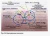
1.3. Application of the superposition principle to the calculation of electrostatic fields. Electrostatic field on the axis of a charged ring
Statement of the problem . Let there be a thin ring of radius R, charged with a linear charge density τ . It is necessary to calculate the electric field strength at an arbitrary point A, located on the axis of the charged ring at a distance x from the plane of the ring (Fig.).

Let us choose an infinitesimal element of the length of the ring dl; charge dq, located on this element is equal to dq=
τ·
dl. This charge creates at a point A electric field strength  . The modulus of the tension vector is equal to:
 .
(1.10)
.
(1.10)
According to the principle of field superposition, the electric field strength created by the entire charged body is equal to the vector sum of all vectors  :
:
 .
(1.11)
.
(1.11)
Let's expand the vectors  into components: perpendicular to the axis of the ring (
  ) and rings parallel to the axis (
  ).
).
 .
(1.12)
.
(1.12)
The vector sum of the perpendicular components is zero:  , Then
  . Replacing the sum with an integral, we get:
 .
(1.13)
.
(1.13)
From the triangle (Fig. 1.2) it follows:
 =
= .
(1.14)
.
(1.14)
Let us substitute expression (1.14) into formula (1.13) and take out the constant values outside the integral sign, we obtain:
 .
(1.15)
.
(1.15)
Because  , That
 .
(1.16)
.
(1.16)
Considering that  , formula (1.16) can be represented as:
 .
(1.17)
.
(1.17)
1.4.Geometric description of the electric field. Tension vector flow
To describe the electric field mathematically, you need to indicate the magnitude and direction of the vector at each point  , that is, set the vector function
  .
.
There is a visual (geometric) way to describe a field using vector lines  (power lines) (Fig. 13.).
Tension lines are drawn as follows:

WITH 
 There is a rule:
electric field strength vector lines, created by the system stationary charges, can begin or end only on charges or go to infinity.
There is a rule:
electric field strength vector lines, created by the system stationary charges, can begin or end only on charges or go to infinity.
Figure 1.4 shows the image electrostatic field point charge using vector lines  , and in Figure 1.5 is an image of the electrostatic field of the dipole .

1.5. Electrostatic field strength vector flow
P  Let us place an infinitesimal area dS in the electric field (Fig. 1.6). Here
  - unit vector normal to the site. Electric field strength vector
  forms with the normal
  some angle α. Vector projection
  to the normal direction is equal to E n =E·cos α .
Vector flow  through an infinitesimal area is called dot product
 ,
(1.18)
,
(1.18)
The electric field strength vector flux is an algebraic quantity; its sign depends on the mutual orientation of the vectors
 And
And
 .
.
Flow vector
 through an arbitrary surface S finite value is determined by the integral:
 .
(1.20)
.
(1.20)
If the surface is closed, the integral is marked with a circle:
 .
(1.21)
.
(1.21)
For closed surfaces, the normal is taken outward (Fig. 1.7).
The flow of the tension vector has a clear geometric meaning: it is numerically equal to the number of lines of the vector
 , passing
through the surface S.
, passing
through the surface S.
General information

We live in an era of synthesized materials. Since the invention of viscose and nylon, chemical industry generously supplies us with synthetic fabrics and we can no longer imagine our existence without them. Truly, thanks to them, humanity has managed to fully satisfy the need for clothing: from fishnet stockings and tights to light and warm sweaters and comfortable and beautiful jackets with synthetic insulation. Synthetic fabrics have a lot of other advantages, which include, for example, durability and water-repellent properties, or the ability to retain their shape for a long time after ironing.
Unfortunately, there is always room for a fly in the ointment in a barrel of honey. Synthetic materials are easily electrified, which we literally feel with our own skin. Each of us, pulling off a faux wool sweater in the dark, could see sparks and hear the crackle of electrical discharges.
Doctors are quite wary of this property of synthetics, recommending the use, at least for underwear, of products made from natural fibers with minimum quantity added synthetics.
Technologists strive to create fabrics with high antistatic properties using various ways reduction of electrification, but the complication of technology leads to an increase in production costs. To control the antistatic properties of polymers, they use various methods measurements of surface charge density, which, along with specific electrical resistance, serves as a characteristic of antistatic properties.
It should be noted that the antistatic properties of clothing and shoes are very important for a certain part of clean production premises, for example, in the microelectronics industry, where electrostatic charges, accumulated during friction of fabrics or shoe materials on their surfaces, can destroy microcircuits.
Extremely high demands applies to the antistatic properties of clothing fabrics and footwear materials oil and gas industry- after all, a small spark is enough to initiate an explosion or fire in such industries. sometimes very severe consequences V materially and even with human casualties.
Historical background
The concept of surface charge density is directly related to the concept of electric charges.
Even Charles Dufay, a scientist from France, in 1729 suggested and proved the existence of charges of various types, which he called “glass” and “resin”, since they were obtained by rubbing glass with silk and amber (that is, tree resin) with wool. Benjamin Franklin, who studied lightning discharges and created the lightning rod, introduced modern names such charges are positive (+) and negative (–) charges.
The law of interaction of electric charges was discovered by the French scientist Charles Coulomb in 1785; now, in honor of his services to science, this law bears his name. In fairness, it should be noted that the same law of interaction was discovered 11 years earlier than Coulomb by the British scientist Henry Cavendish, who used the same ones developed by him for experiments torsion scales, which Coulomb later independently applied. Unfortunately, Cavendish's work on the law of interaction of charges for a long time(over a hundred years) was unknown. Cavendish's manuscripts were published only in 1879.
The next step in the study of charges and calculations of the electric fields they create was made by the British scientist James Clerk Maxwell, who combined Coulomb's law and the principle of field superposition with his electrostatic equations.
Surface charge density. Definition
Surface charge density is a scalar quantity that characterizes the charge per unit surface of an object. Its physical illustration, to a first approximation, can be a charge on a capacitor made of flat conducting plates of a certain area. Since charges can be both positive and negative, their surface charge density values can be expressed as positive and negative values. It is designated Greek letterσ (pronounced sigma) and is calculated using the formula:
σ = Q/S
σ = Q/S where Q is the surface charge, S is the surface area.
Dimension of surface charge density in International system SI units are expressed in coulombs per square meter(C/m²).
In addition to the basic unit of surface charge density, a multiple unit (C/cm2) is used. Another measurement system - SGSM - uses the unit abculon per square meter (abC/m²) and a multiple unit abculon per square centimeter(abC/cm²). 1 abcoulomb is equal to 10 coulombs.
In countries where they are not used metric units area, surface charge density is measured in coulombs per square inch (C/in²) and abcoulombs per square inch (abC/in²).
Surface charge density. Physics of phenomena
Surface charge density is used to carry out physical and engineering calculations of electric fields in the design and use of various electronic experimental facilities, physical devices and electronic components. As a rule, such installations and devices have plane electrodes made of conductive material of sufficient area. Since the charges in a conductor are located along its surface, its other dimensions and edge effects can be neglected. Calculations of electric fields of such objects are carried out using Maxwell's equations of electrostatics.
Surface charge density of the Earth
Few of us remember the fact that we live on the surface of a giant capacitor, one of the plates of which represents the surface of the Earth, and the second plate is formed by ionized layers of the atmosphere.
That is why the Earth behaves like a capacitor - it accumulates an electric charge and in this capacitor, from time to time, breakdowns of the interelectrode space even occur when the “operating” voltage is exceeded, better known to us as lightning. The Earth's electric field is similar to the electric field of a spherical capacitor.
Like any capacitor, the Earth can be characterized by a surface charge density, the value of which, in general, can vary. In clear weather, the surface charge density on a particular area of the Earth approximately corresponds to the average value for the planet. Local values of the surface charge density of the Earth in the mountains, on hills, in places where metal ores and at electrical processes in the atmosphere may differ from the average values upward.
Let us estimate its average value under normal conditions. As you know, the radius of the Earth is 6371 kilometers.
Experimental studies of the Earth's electric field and corresponding calculations show that the Earth as a whole has a negative charge, the average value of which is estimated at 500,000 coulombs. This charge is maintained at approximately the same level due to a number of processes in the Earth's atmosphere and in nearby space.
According to the famous school course formula calculate the surface area globe, it is approximately equal to 500,000,000 square kilometers.
Hence the average surface charge density of the Earth will be approximately 1 10⁻⁹ C/m² or 1 nC/m².

Kinescope and oscilloscope tube
Television would have been impossible without the advent of devices that ensure the formation of a narrow beam of electrons with high density charge - electron guns. Until recently, one of the main elements of televisions and monitors was a kinescope, or, in other words, a cathode ray tube (CRT). CRT production on an annualized basis amounted to hundreds of millions of units in the recent past.
A kinescope is an electron-vacuum device designed to convert electrical signals into light signals to dynamically form an image on a phosphor-coated screen, which can be monochrome or polychrome.
The design of the kinescope consists of an electron gun, focusing and deflection systems, accelerating anodes and a screen with a phosphor layer applied. In color picture tubes (CELT), the number of elements creating electron beams is tripled by the number of displayed colors - red, green and blue. Color picture tube screens have slot or dot masks that prevent electron beams of a different color from reaching a specific phosphor.

The phosphor coating is a mosaic of three layers of phosphors with different color luminescence. Mosaic elements can be located in the same plane or at the vertices of the display element triangle.
An electron gun consists of a cathode, a control electrode (modulator), an accelerating electrode, and one or more anodes. When there are two or more anodes, the first anode is called the focusing electrode.
The cathode of picture tubes is made in the form of a hollow sleeve, on outside the bottom of which is coated with an oxide layer of oxides alkaline earth metals, providing sufficient thermal emission of electrons when heated to a temperature of about 800 °C due to a heater electrically isolated from the cathode.
The modulator is a cylindrical glass with a bottom covering the cathode. In the center of the bottom of the glass there is a calibrated hole of about 0.01 mm, called the carrier diaphragm, through which the electron beam passes.
Since the modulator is located a short distance from the cathode, its purpose and operation is similar to the purpose and operation of the control grid in a vacuum tube.
The accelerating electrode and anodes are hollow cylinders, the last anode is also made in the form of a sleeve with a calibrated hole at the bottom, which is called the output diaphragm. This system of electrodes is designed to give electrons the required speed and form a small spot on the kinescope screen, representing an electrostatic lens. Its parameters depend on the geometry of these electrodes and the surface charge densities on them, which are created by applying appropriate voltages to them relative to the cathode.

One of the recently widely used electronic devices was an oscillographic cathode ray tube (OCRT), designed to visualize electrical signals by displaying them with an electron beam on a fluorescent monochrome screen. The main difference between an oscilloscope tube and a kinescope is the principle of constructing a deflection system. In OELT it is used electrostatic system deviations because it provides greater performance.

An oscillographic CRT is an evacuated glass bulb containing an electron gun, which generates a narrow beam of electrons using a system of electrodes that deflects the electron beam and accelerates it, and a luminescent screen that glows when bombarded by accelerated electrons.
The deflection system consists of two pairs of plates located horizontally and vertically. The voltage being tested is applied to the horizontal plates - otherwise known as the vertical deflection plates. The vertical plates - otherwise the horizontal deflection plates - are supplied with a sawtooth voltage from the scan generator. Under the influence of voltages on the plates, a redistribution of charges occurs on them and, due to the resulting total electric field (remember the principle of field superposition!), flying electrons deviate from their original trajectory in proportion to the applied voltages. The electron beam draws the shape of the signal being studied on the tube screen. Due to the sawtooth voltage on the vertical plates, the electron beam, in the absence of a signal on the horizontal plates, moves across the screen from left to right, while drawing a horizontal line.

If two different signals are applied to the vertical and horizontal deflection plates, then the so-called Lissajous figures can be observed on the screen.
Since both pairs of plates form flat capacitors, the charges of which are concentrated on the plates, to calculate the design of a cathode ray tube, the surface charge density is used, which characterizes the sensitivity of electron deflection to the applied voltage.
Electrolytic capacitor and ionistor
Surface charge calculations must also be performed when designing capacitors. In modern electrical engineering, radio engineering and electronics, capacitors of various types are widely used, used to separate DC and DC circuits. AC and for accumulation electrical energy.
The storage function of a capacitor directly depends on the size of its capacity. A typical capacitor consists of plates of conductor called capacitor plates (usually made of various metals), separated by a dielectric layer. The dielectric in capacitors is solid, liquid or gaseous substances having high dielectric constant. In the simplest case, the dielectric is ordinary air.
We can say that the storage capacity of a capacitor for electrical energy is directly proportional to the surface charge density on its plates or the area of the plates, and inversely proportional to the distance between its plates.

Thus, there are two ways to increase the energy accumulated by the capacitor - increasing the area of the plates and reducing the gap between them.
In electrolytic capacitors of large capacity, a thin oxide film is used as a dielectric, deposited on the metal of one of the electrodes - the anode - the other electrode is the electrolyte. Main feature electrolytic capacitors is that, compared to other types of capacitors, they have a large capacity with fairly small dimensions, in addition, they are polar electrical storage devices, that is, they must be included in electrical circuit observing polarity. The capacity of electrolytic capacitors can reach tens of thousands of microfarads; for comparison: the capacity of a metal ball with a radius equal to the radius Earth is only 700 microfarads.

Accordingly, the surface charge density of such energized capacitors can reach significant values.
Another way to increase the capacitance of a capacitor is to increase the surface charge density due to the developed surface of the electrodes, which is achieved by using materials with increased porosity and using the properties of a double electrical layer.
The technical implementation of this principle is an ionistor (other names are supercapacitor or ultracapacitor), which is a capacitor, the “plates” of which are a double electrical layer at the interface between the electrode and the electrolyte. Functionally, the ionistor is a hybrid of a capacitor and chemical source current
An interfacial electrical double layer is a layer of ions formed on the surface of particles as a result of the adsorption of ions from a solution or the orientation of polar molecules at the phase boundary. Ions directly bonded to the surface are called potential-determining. The charge on this layer is balanced by the charge on a second layer of ions called counterions.
Since the thickness of the electrical double layer, that is, the distance between the “plates” of the capacitor, is extremely small (the size of an ion), the energy stored in the supercapacitor is higher compared to conventional electrolytic capacitors of the same size. In addition, the use of a double electrical layer instead of a conventional dielectric allows one to significantly increase the effective surface area of the electrode.
While typical ionistors are inferior to electrochemical batteries in terms of stored energy density, promising developments of supercapacitors using nanotechnology have already matched them in this indicator and even surpassed them.
For example, airgel supercapacitors developed by Ness Cap., Ltd with carbon foam electrodes have a volumetric capacity that is 2000 times greater than the volumetric capacity of an electrolytic capacitor of the same size, and the specific power exceeds the specific power of electrochemical batteries by 10 times.
Other valuable qualities of a supercapacitor as an electrical energy storage device include low internal resistance and very low leakage current. In addition, the supercapacitor has a short charging time, allows high discharge currents and a virtually unlimited number of charge-discharge cycles.
Supercapacitors are used for long-term storage of electrical energy and when powering loads with high currents. For example, when utilizing the braking energy of Formula 1 racing cars with subsequent recovery of the energy accumulated in the ionistors. For racing cars, where every gram and every cubic centimeter volume, supercapacitors with a stored energy density reaching 4000 W/kg are an excellent alternative to lithium-ion batteries. Ionistors have also become commonplace in passenger cars, where they are used to power equipment during starter operation and to smooth out voltage surges during peak loads.
Experiment. Determination of surface charge density of coaxial cable braid
As an example, consider the calculation of the surface charge density on the braid of a coaxial cable.
To calculate the surface charge density accumulated by the braid of a coaxial cable, taking into account the fact that the central core together with the braid form a cylindrical capacitor, we use the dependence of the capacitor charge on the applied voltage:
Q = C U where Q is the charge in coulombs, C is the capacitance in farads, U is the voltage in volts.
Let's take a piece of radio-frequency coaxial cable of small diameter (at the same time its capacitance is higher and it is easier to measure) with a length L equal to 10 meters.
Using a multimeter, measure the capacitance of a piece of cable, and using a micrometer, measure the diameter of the braid d
Sk = 500 pF; d = 5 mm = 0.005 m
Let's apply a calibrated voltage of 10 volts to the cable from the power source, connecting the braid and central core of the cable to the terminals of the source.
Using the above formula, we calculate the charge accumulated on the braid:
Q = Сk Uk = 500 10 = 5000 pC = 5 nC
Considering the braid of a cable segment to be a solid conductor, we find its area, calculated using the well-known formula for the area of a cylinder:
S = π d L = 3.14 0.005 10 = 0.157 m²
and calculate the approximate surface charge density of the cable braid:
σ = Q/S = 5/0.157 = 31.85 nC/m²

Naturally, as the voltage applied to the braid and central core of the coaxial cable increases, the accumulated charge also increases and, consequently, the surface charge density also increases.
Electrostatics. Application of the Ostrogradsky–Gauss theorem to calculate fields in vacuum
Coulomb's law allows you to calculate the field of any system of charges, i.e., find its intensity at any point by summing vectorially the intensities created by individual charges (since intensity vectors obey the principle of superposition). Tension is called vector physical quantity, characterizing the force of the electrostatic field on a positive charge. The direction of the tension vector coincides with this force. For problems that have symmetry, the calculations can be greatly simplified; in these cases, it is convenient to use the Ostrogradsky–Gauss theorem for the flow of the intensity vector through some closed surface (Fig. 1.1). Let all charges Q i be concentrated inside a closed surface with area S.
On a surface element with area dS, the charges create a corresponding intensity, and the total
tension is equal to .
Flow Ф of the intensity vector through the closed surface under consideration
The flows of tension vectors (scalars) are summed algebraically. Taking into account the values of Ф i, we can rewrite:
where (is the unit vector of the external normal to the surface element with area dS); is the projection of the vector; Q i are the charges located inside the surface.
![]()
The Ostrogradsky–Gauss theorem is formulated as follows. The vector flux through any closed surface is proportional to the total charge located inside this surface.
There are three possible cases when the flux of the tension vector through a closed surface vanishes:
A) algebraic sum charges inside the surface is zero, ;
b) there are no charges inside the surface, but there is a field associated with external charges; c) there is no field or internal charges.
Charges can be distributed in different ways, and they can be brought into the space under consideration, move in it and be removed from it, which is why they are called free charges.
If the charge dQ is continuously distributed in some small volume dV. In this case, the concept of volumetric charge density is introduced
ρ = dQ/dV (expressed in coulombs per cubic meter). If the charges are continuously distributed over the surface of the conductor, then the concept of surface density σ = dQ/dS is introduced, where dS is the area of the conductor surface element on which the elementary charge dQ is located. The unit of surface density is 1 C/m2. If the charges are uniformly distributed along the line, in this case the concept of linear charge density λ = dQ/dl is introduced, where dl is the length of the line segment on which the charge dQ is distributed. The unit of linear density is 1 C/m.
The voltage vector on the surface of a charged conductor is always perpendicular to the surface (for example, for a charged ball, Fig. 1.2), since otherwise the charges would move along the surface under the influence of the tangential component of the voltage. Thus, at the surface of the conductor
and inside a solid conductor

Rice. 1.2. Field of a charged metal ball
If the charges are distributed throughout the volume of the dielectric with bulk densityρ, then the Ostrogradsky–Gauss theorem is written as:
where dV is a volume element; V is the volume limited by the surface S.
When the charges are distributed over the surface of the conductor, and the integration surface coincides with the latter, then

 .
.
Then the voltage on the surface of the conductor is proportional to the surface charge density:
Positive field point charge has spherical symmetry relative to the point at which it is located, and is characterized by tension directed along radii drawn from this point and equal to
i.e., it obeys Coulomb’s law (for negative charge the vector is directed towards this point). The field of a charged metal ball is subject to the same laws. The charge on the ball is distributed evenly over the surface. Then for a metal ball with radius R 0 the field strength is determined in accordance with formula (1.2).
If there is a cavity inside a charged ball or other metal conductor into which no charges are introduced, then the field inside this cavity cannot be created by charges located on the surface of the conductor. Since the field inside the cavity is not associated with any charges, it is absent, i.e. E field = 0.

Of practical interest is the field created by a long uniformly charged wire (cylinder) of radius R 0 (Fig. 1.3). By choosing the integration surface in the form of a coaxial cylinder of radius R and height h and introducing the linear charge density
We are convinced that, due to cylindrical symmetry, the tension on the side surface of the cylinder is everywhere the same in magnitude and directed along the radii, and there is no tension flow through the bases.
In this case, the field strength varies in inverse proportion to the first power of the distance. On the surface of the wire we get

Let us now find the field strength of a boundless flat metal plate (Fig. 1.4). Let the plate be uniformly charged. As the surface of integration we choose the surface
rectangular parallelepiped, two faces of area S are parallel to the charged plate. The surface charge density is
σ = Q /2S, since the plate has two sides and the charge is distributed on both sides. Due to symmetry, the flux of the tension vector for the faces is nonzero. Hence,
For two parallel plates (Fig. 1.5), having the same charge density in absolute value, using the superposition principle we obtain: a) for the field between the plates
b) for the field outside the plates
![]() .
.

We can conclude that the charges are collected on the sides of the plates facing each other with a surface density σ1 = σ. The tension determined by expression (1.3) does not depend on the distance and is the same at all points. Such fields are called homogeneous. There are no real infinite wires and plates, but the resulting formulas retain their value for regions sufficiently close to charged bodies (the distance to the field point under study should be much less than the linear size of the charged body). The distribution of tension lines can be obtained experimentally by placing electrodes of one shape or another in a liquid dielectric (vaseline oil) and pouring fine dielectric powder (quinine) onto the surface of the oil. In this case, the powder particles are located approximately along the tension lines.
The Ostrogradsky–Gauss theorem can be used not only in integral form, connecting the values of intensity E at some points of the field with charges located at other points, but also in differential form. Let us connect the quantities related to the same point in the field.
Let there be tension at some point A with coordinates (x,y,z) ![]() where i , j , k are direction vectors in Cartesian system coordinates
where i , j , k are direction vectors in Cartesian system coordinates
Let us select a rectangular parallelepiped of infinitesimal volume near point A (Fig. 1.6)dV = dx`dy`dz.

Rice. 1.6. On the Ostrogradsky–Gauss theorem
The volumetric charge density in it is equal to ρ. It depends on the coordinates of the selected field point p = f (x,y,z). Flow vector through the right
 . In the same way for the top and bottom edges we get
 ![]() ,
,

and for the back and front faces ![]() . Let us apply the Ostrogradsky–Gauss theorem to this volume:
. Let us apply the Ostrogradsky–Gauss theorem to this volume:
 ,we finally get the expression
  . In vector analysis, the amount worth
In this form the theorem is applicable to individual points of the field.
The Ostrogradsky–Gauss theorem is not a consequence of Coulomb's law. It is one of the main theorems of vector analysis, connecting the volume integral with the surface integral. In physics, this theorem applies to central forces, depending on the distance according to the law R n, where n is any number. Thus, Coulomb's law is a special case of the Ostrogradsky–Gauss theorem.
Let's consider the work of electrostatic forces when moving a particle with charge q from one field point to another along an arbitrary path 1A 2 (Fig. 1.7):
where E i is the projection of the direction vector dl. This work will depend only on the position of the initial and end points path, and not from its form, i.e. the field is potential:

where φ1, φ2 are the potentials of the initial and final points of the trajectory. Potential is a scalar characteristic of a field point. U = φ1 – φ2 – potential difference or change potential energy a unit positive charge transferred in an electrostatic field.
Thus, the work of electrostatic forces is proportional to the potential difference U at the starting and ending points of the path. The unit of potential and potential difference is the Volt (V).
The work of electrostatic forces along any closed path is zero:
This integral is called the circulation of the tension vector. Equality to zero circulation means that there are no closed lines of tension in the electrostatic field: they begin and end on charges (positive or negative, respectively) or go to infinity.
In an electrostatic field, it is possible to construct (Fig. 1.7) surfaces that represent a set of points of equal potential (equipotential surfaces). Let us prove that the tension lines are normal to these surfaces. If you move a charge along an equipotential surface, then the work will be zero. But the field strength at the surface can be different from zero. Therefore, from the definition of elementary work
it follows that when  , therefore, and the vector dl is directed tangentially to the surface.
Consequently, at all points of a surface of equal potential, the tension is directed normal to this surface. From calculating the fields of symmetrical conductors using the Ostrogradsky–Gauss theorem, it is clear that the surface of a conductor in an electrostatic field is always equipotential.
The electrostatic field strength is related to the potential at each point of the field by the relation