Magnetism is considered the most interesting and promising phenomenon in nature, which can manifest itself through various types fields. Electromagnetic fields are just one type of field. They are formed from two types of fields, electric and magnetic. Let's begin to understand the nature and principle of the action of magnetic fields. The easiest way to use permanent magnets and electromagnets as a source of magnetic fields. But we’ll talk about how they work.

An electromagnet is a simple electrical structure consisting of a winding and a core. From the course of electrical engineering it is known that when an electric current passes through a winding, electromagnetic fields arise around it.
That is, at the time when electrical charge As it moves, it generates magnetic fields around itself. When it is not moving, it only has an electric field. But, electrons and ions will never be in a state of complete rest. There is always internal motion, so the electric and magnetic fields are present simultaneously, only in the case relative peace V to a greater extent noticeable electric fields, and with increasing movement elementary particles The magnetic field begins to dominate.
Thus, to create a magnetic field, you only need to pass current through the conductor, and to increase the level of intensity of this field, you need to increase the current strength or length electrical conductor. But there is another factor that affects the strength of the magnetic field.
In addition to the above, electromagnets have a core made of magnetic material. Such a magnetic material carries out its own internal movement of charged elementary particles. But they are arranged in a chaotic order, which causes mutual cancellation of magnetic forces.
When exposed to external electromagnetic field the following effect occurs on such a material, namely, all internal magnetic fields of this material rotate in one direction, which leads to a sharp increase magnetic properties. Therefore, to make a good magnet, you need to wind large number turns of copper wire, then pass current through them.

But remember that when the voltage is turned off, the electromagnet loses all its properties. Because all charged particles stop moving in the conductor, and the ordered magnetic fields inside the magnetic core return to their original chaotic state. For making permanent magnet without power supply, it is required that the internal magnetic fields remain in a unidirectional state. This can be achieved using special magnetic materials, which can be magnetized or demagnetized.
At the initial moment, this substance does not have such strong magnetic properties. To magnetize it, it must be placed in a strong constant magnetic field. After a certain period of time and intensity of exposure, this material becomes a permanent magnet. To demagnetize a permanent magnet, it must be subjected to high temperature, strong impacts or exposure to strong alternating magnetic fields.
I think everyone has encountered ordinary permanent magnets. Do you know what is the real reason their specific action? I think not many people know about this. Offering you to get acquainted with a simple theoretical lecture about the structure of a permanent magnet and the magnetic field
In principle, their calculation is enough complex process, but for radio amateurs, it is significantly simplified. The magnetic circuit is described by the quantity - IN, which is influenced by the field strength and magnetic permeability of the substance. Therefore, the cores of electromagnets are made of a special iron alloy with a high magnetic permeability. The power flux depends on magnetic induction, F.
Where, S is the cross-sectional area of the magnetic circuit. Magnetomotive force also influences the power flow (E m), which is calculated by the formula:
Ф = (E m) × R m, from where E m = 1.3 × I × N
Where, where N- the number of turns of the coil, and I- the strength of the current flowing through the coil in amperes.
Magnetic resistance is determined by the formula:
where L - average length power paths magnetic lines, M is the magnetic permeability, and S is the cross-section of the magnetic circuit.
When making homemade electromagnets, they try to obtain the maximum power flow. This is achieved by reducing magnetic resistance. Why choose a magnetic core with a minimum path length? power lines and with the maximum possible cross section, and the material is steel alloy with excellent magnetic permeability. Another method of increasing the power flow is to increase the number of ampere turns, which is not very practical, because in order to save wire and supply voltage, one should strive to reduce the number of ampere turns. Suppose we need to determine the ampere turns and power flux of a closed steel magnetic circuit, shown in figure a below, and made of poor quality steel.

To wind coils with a minimum number of turns, for simplified calculations we will assume a magnetic induction value of 10,000 lines of force per 1 cm 2 with two ampere turns per centimeter of length. In this amateur radio example, the calculation can be done as follows. So, with the length of the magnetic circuit L =L1+L2 equal to 20 cm + 10 cm = 30 cm, 2 × 30 = 60 ampere turns will be required.
If the core diameter D(Figure c) is 2 cm, then its area is: S = 3.14xD2/4 = 3.14 cm 2, from here
Ф = B × S = 10000 × 3.14 = 31400 power lines
.It is possible to approximately determine the lifting force of an electromagnet P:
P = B2 × S/25 × 1000000 = 12.4 kg.
For a two-pole magnet, the result obtained must be doubled. When calculating the lifting force of a magnet, it should be remembered that it depends not only on the length of the magnetic circuit, but also on the contact area of the armature and the core. Therefore, the anchor must fit well to the pole pieces of the EM, otherwise a sharp decrease in lift will occur. Next, you can calculate the electromagnet coil. In the case of a two-pole magnet, a lifting force of 25 kg is given by 60 ampere turns, i.e. N×J = 60 ampere turns.
Of course, you can set another ratio, for example, 2 A and 30 turns, or by increasing the number of turns of the coil 0.25 A and 240 turns. However, changing the current rating over a wide range is not always possible in practice, since a very large diameter of the wire used may be required. In our example, the copper wire should have the following cross-section: for a current of 2A - 0.4 mm 2, and for a current of 0.25 A - 0.05 mm 2, the wire diameter will be 0.7 mm and 0.2 mm, respectively. Which of these wires is better for winding? Knowing the diameter of the wire and its length, you can easily find the resistance. The wire length L is calculated as the product total number turns per length of one of them (average): L = N × L1 where L1 is the length of one turn, equal to 3.14 × D. In our example, D = 6.3 cm. Therefore, for the first coil, the length of the copper wire will be 190 cm, and the winding resistance to direct current will be about 0.1 Ohm, and for the second is 512 cm, with a resistance of 8.7 Ohms. Knowing Ohm's law, it is easy to find the desired voltage. So, to create a current in the windings with a nominal value of 2A, a voltage of 0.2V will be required, and for a current of 0.25A - 2.2V.
Chapter 21
ELECTROMAGNETIC ACTUATORS
§ 21.1. Purpose of electromagnetic actuators
Actuators in automation systems are designed to actuate (i.e., drive) various regulatory bodies that have a direct impact on the control object in order to achieve the required value of the output value of this object. There is a wide variety of regulatory bodies: to change the supply of liquids and gases, dampers, valves, gates and taps are installed in pipelines; in lifting and transport devices these are various contactors, couplings, brakes, speed variators; in lighting and heating electrical installations these are various switching devices.
To influence the regulatory bodies, it is necessary to perform mechanical work: turn the valve or valve, connect the two halves of the coupling, move the gear on the gearbox shaft, close the contacts, etc. The input signal of the actuator in electrical systems automation is electric current or voltage, and the output signal - mechanical movement.
To convert electrical energy The mechanical part consists of electromagnets and electric motors. In this chapter, only electromagnetic actuators will be considered. Electric motors are electrical machines and are studied in the appropriate course. It should be noted that almost always, when the question of developing a drive for a regulatory body is raised, a choice has to be made between two options: an electromagnet or an electric motor. The main advantage of an electromagnet is its simplicity of design. U The electric motor has more advantages: high efficiency, the ability to achieve any speeds and movements. However, these advantages appear only in relatively complex systems automation and during continuous operation. If it is necessary to have small movements (a few millimeters) and forces (several tens to hundreds of newtons), electromagnets are more profitable than an electric motor with a gearbox.
IN previous chapters electromagnets used as component electromagnetic relays and contactors. This chapter will cover general questions classification of electromagnets, their calculation, design, use as actuating elements of automation systems.
§ 21.2. Classification of electromagnets
Depending on the type of current in the winding, electromagnets are divided into direct and alternating current electromagnets, and according to the operating speed - into high-speed, normal and slow-acting. According to their purpose, electromagnets are divided into driving and holding.
Drive electromagnets are used to perform mechanical work. When power is applied, they move various actuators: valves, pushers, dampers, spools, railroad switches. They move relay and contactor contacts, printing and punching devices. To do this job, electromagnets must be designed to withstand a certain amount of force and movement.
Holding electromagnets They do not serve to move, but only to hold ferromagnetic parts. For example, the electromagnet used in lifting scrap iron only holds it, and the movement is carried out by the lifting crane. In this case, the electromagnet only serves as a crane hook. In metalworking, electromagnetic plates are used to fix the workpiece on the machine. Electromagnetic locks are also known. Since holding electromagnets do not perform work, they are designed only for a certain force. In some cases, the electromagnet has two coils: one, more powerful, is used to move the armature, and the other is used only to hold the armature in an attracted position.
There is a wide variety of special-purpose electromagnets. They are used to focus electron beams in television, in particle accelerators, in a variety of measuring instruments, in medical equipment, etc.
According to their design, there are valve (rotary), linear, and electromagnets with transverse movement. Valve electromagnets have a small armature movement (a few millimeters) and develop a large traction force.
Straightforward electromagnets have a large armature stroke and greater speed; they are smaller in size than valve ones. They are often in the form of a solenoid (a cylindrical coil that draws in a ferromagnetic rod), so they are sometimes called solenoid electromagnets.
Rice. 21.1. Options for design diagrams of electromagnets
Various designs electromagnets are shown in Fig. 21.1. Despite their great variety (not all possible designs are shown in this figure), they all consist of a coil 1, armature (moving magnetic circuit) 2, fixed magnetic circuit (core 3 and yoke 4). In addition, they have various springs, fastening, fixing and transmitting parts, and a housing. According to the design of the magnetic circuit, electromagnets with an open circuit are distinguished (Fig. 21.1, d, f) and a closed magnetic circuit (Fig. 21.1, a, b, c, d, g, h). Based on the shape of the magnetic core, electromagnets with U-shaped, W-shaped and cylindrical magnetic cores are distinguished.
Magnetic cores of electromagnets DC are usually made solid from soft magnetic materials: conventional structural steels and low-carbon electrical steels. Highly sensitive electromagnets have a magnetic core made of permalloy (iron alloys with nickel and cobalt). In high-speed electromagnets they tend to reduce eddy currents, for which electrical silicon steels with increased electrical resistance and a laminated (composited) magnetic circuit.
To reduce losses on eddy currents magnetic circuit of electromagnets AC assembled (mixed) from insulated plates 0.35 or 0.5 mm thick. The material used is hot-rolled and cold-rolled electrical steel. Individual parts of the magnetic circuit, which are difficult to make laminated, are made of solid material 2-3 mm thick.
Electromagnet coils can be framed or frameless in design, and round or rectangular in cross-sectional shape. The wire of the frame coil is wound onto a frame made of insulating material (textolite, getinax, plastic). The wire of a frameless coil is wound directly onto a core wrapped with insulating tape, or onto a special template. To ensure the strength of the coil made on the template, it is wrapped with tape (padded) and impregnated with compound varnish. Reels are usually wound copper wire with insulation selected based on the purpose and operating conditions of the electromagnet.
Depending on the connection method, serial and parallel coils are distinguished. Parallel coils have large number turns and are wound with a thin wire. They are usually switched on at full mains voltage. Series coils have a relatively low resistance, since they are made of thick wire and a small number of turns. The current of such a coil is not determined by its resistance, but depends on the devices with which the coil is connected in series.
There are also electromagnets designed for long-term, short-term and intermittent operation.
§ 21.3. The procedure for design calculation of an electromagnet
The initial data for calculating the electromagnet is usually the required traction force F e, armature travel (or rotation angle) and supply voltage U. In addition, the design specifications indicate the operating mode of the electromagnet and operating conditions. The required speed, dimensions, weight, and cost can be specified.
As a result of the calculation, it is necessary to select the design of the electromagnet, the material of the magnetic core, determine the geometric dimensions of the magnetic core and coil, and winding data.
At the first stage of the design calculation, it is necessary to select the design of the electromagnet using the concept design factor A. This value is determined depending on the traction force and the armature stroke:
|
|

where - in N; - in cm
When using a forward-moving solenoid-type electromagnet; with - straight forward with conical foot; with - straight forward with flat stop; at 2.6<<26 - с поворотным якорем клапанного типа.
The shape of the electromagnet is selected taking into account the required traction characteristics. In Fig. 21.2 shows typical traction
characteristics of electromagnets. If it is necessary to have a flat traction characteristic 1, then a forward stroke electromagnet should be used if the 2 - valve solenoid. The W-shaped electromagnet (5) is used primarily in alternating current circuits.
At the second stage, the induction is selected and the cross-section of the magnetic circuit is determined.
The attractive force of the armature is mainly created by the magnetic flux in the air gap. Therefore, during design calculations, the influence of stray flows on the traction force is usually not taken into account. The optimal magnetic flux and induction in the working air gap can be within very wide limits and depends on the relationship between the traction force and the stroke, i.e. on the design factor A. In Fig. Figure 21.3 shows the dependences of induction on the design factor for three designs of electromagnets (with a flat stop, with a conical stop, and valve type). Once selected, the cross-sectional area of the pole piece can be determined from these induction curves. Let us recall formula (17.13), which relates the traction force by induction in the gap and the cross-section of the pole piece. When determining the diameter of the core, it is necessary to first specify the induction in the steel and the dissipation coefficient of the magnetic system. For powerful electromagnets it is taken within , for small magnetic relay systems - within . Dissipation coefficient Smaller values are taken for small armature strokes, larger values for movements of several centimeters. The cross section of the core is determined by the formula
The cross section of the yoke is usually taken equal to the cross section of the core, and the cross section of the armature is taken to be smaller:

Rice. 21.3. Dependence of induction in the gap of the electromagnet and the dimensions of the coil on the value of the design factor
required traction force. Let us introduce the coefficient, which is the ratio of the MMF that is not involved in the creation of traction force to the total MMF of the coil. Then, assuming the conductivity of the air gap, we determine the total MMF of the coil:
It can be refined when calculating the magnetic circuit using magnetization curves for the selected magnetic core material.
The ratio of the height of the winding space of the coil to his The width is usually selected according to the design factor (lower curve in Fig. 21.3). Specific coil sizes are selected based on the heating conditions of the coil. This takes into account the operating mode, heat transfer coefficient, winding method, which affects the fill factor, and wire insulation, which determines the permissible temperature. In addition, it is necessary to take into account the possibility of reducing the supply voltage to
Taking these factors into account, the width of the coil winding space is determined by the formula
Knowing the dimensions of the coil, it is possible to determine all the dimensions of the magnetic circuit of the electromagnet: the height of the core and yoke, the distance between them, etc.
§ 21.4. Features of calculating AC electromagnets
IN In alternating current electromagnets, the induction in the magnetic circuit varies according to a sinusoidal law. Since the maximum (amplitude) value of induction is several times greater than the effective value, and the magnitude of the traction force is proportional to the square of the induction, an alternating current electromagnet with the same degree of saturation of the magnetic circuit develops half the value of the traction force. Therefore, when determining the design factor for an alternating current electromagnet, double the value of the traction force is taken."
Optimal ratios between the height and width of the coil winding space t =h/a turn out to be smaller than for DC electromagnets. Therefore, the coils of the AC electromagnets will be shorter and thicker. A shorter coil reduces core length and volume, resulting in reduced steel losses caused by hysteresis and eddy currents. These losses did not exist in DC electromagnets. There they sought to reduce losses in copper, which was ensured by reducing the average length of the coil turn due to its small thickness. In AC electromagnets, one must strive to reduce the total losses (both in copper and steel).
When making a more precise calculation of electromagnets, it is necessary to take into account the leakage fluxes and the drop in MMF in non-working gaps and in steel. In addition, in AC electromagnets it is necessary to take into account losses due to hysteresis and eddy currents in the magnetic core
These losses are proportional to the supply frequency, the mass of the magnetic circuit and the squared induction. For materials used in the magnetic circuit of an electromagnet, specific losses (depending on sheet thickness and frequency) per unit mass are given in reference books.
Number of turns of AC electromagnet winding
|
|

![]() (21.7)
(21.7)
The diameter of the wire is determined by the current density permissible from the point of view of heating. In this case, the current is determined taking into account losses in steel:
where is the loss current in steel; -magnetizing current.
The values of and can be determined using the electrical equivalent circuit of the electromagnet (Fig. 21.4). The following designations are used in the diagram: - active resistance of the winding;
Inductive reactance corresponding to the working flow; - inductive reactance corresponding to the leakage flux; -active resistance caused by losses in the magnetic circuit due to hysteresis and eddy currents.
|
|

|
|

|
|

If we neglect the voltage drop across the active resistance of the winding and the leakage flux, then the loss current
![]() (21.9)
(21.9)
The magnetizing current that creates the working magnetic flux is determined by MMF (). If we neglect the drop in MMF in steel and non-working gaps, then
where-acting ![]() the value of the alternating magnetic flux in the working gap; -magnetic conductivity of the working gap.
the value of the alternating magnetic flux in the working gap; -magnetic conductivity of the working gap.
A preliminary calculation of an electromagnet with a short-circuited turn is carried out without taking into account the shielding effect of this turn. Accurate calculation of the parameters of a short-circuited turn is quite complicated. In practice, it is made of copper or brass in such a way that it covers approximately the poles of the electromagnet. With a W-shaped magnetic circuit, a short-circuited turn 3 located on the middle (Fig. 21.5, A) or on the outermost rods (Fig. 21.5, b). The widely used electromagnets of the MIS series are made with a coil on the middle rod. To reduce the drop in MMF in the non-working gap between the armatures and the core 2 there is a so-called collar 5. The nominal traction force of electromagnets of the MIS series varies from 15 to 120 N with an armature stroke of 15-30 mm. Mechanical wear resistance is approximately 10 6 on-off cycles.
With turns on the outer rods (Fig. 21.5, b) Long-stroke electromagnets of the ED series were manufactured. They have a T-shaped anchor 1. Traction force cos  is given in all three rods, i.e. the magnetic circuit contains three working gaps. The traction force of electromagnets of the ED series reaches 250 N with a maximum armature movement of up to 40 mm. Electromagnets are triggered when current is applied to the winding 4.
§ 21.5. Electromagnetic couplings
The electromagnetic clutch is designed to transmit engine torque to the operating mechanism. The coupling consists of two parts: driving and driven, which form a closed magnetic system. The coupling is made of ferromagnetic materials and has one or more field windings.
Distinguish friction couplings and asynchronous(induction) couplings. In friction clutches, rotation is transmitted due to the friction force between the driving part, mounted on the electric motor shaft, and the driven part, which can move along the shaft of the operating mechanism on splines or a key. When current is supplied to the excitation winding, a magnetomotive force is created and the moving part of the coupling is pressed against the stationary one. This clutch works like an electromagnet. To transmit significant torques, multi-disc designs of electromagnetic couplings are used. Both on the drive and driven shafts there are several steel disks, which, under the action of the MMF, are attracted to each other and, due to the friction of their surfaces, rotation is transmitted. The contacting surfaces of friction clutches are made of a special material - Ferrado alloy, which has a friction coefficient 3-4 times greater than that of steel.
There are designs of electromagnetic friction clutches with a stationary electromagnet coil and with a rotating coil.
In low-power couplings (Fig. 21.6, A) master 1 and slave 2 coupling halves do not have windings, but one of them (usually the driven one) can move along the shaft along a key or spline. Both clutches are surrounded by a stationary electromagnet coil 3, which when connected to voltage creates a magnetic flux. The resulting electromagnetic forces press the driven coupling half to the driving half. The frictional moment between the coupling halves must be greater than the load moment on the driven shaft. When the clutch coil is disconnected, the stationary coupling half is pressed away from the movable half using a spring (not shown in the figure). Usually the same spring presses the clutch half against the braking surfaces, which

ensures quick stopping of the driven shaft. In powerful couplings (Fig. 21.6, b), several steel disks are used in the moving part of the coupling to increase the amount of transmitted torque 2, having freedom of movement along the axis of rotation of the drive and driven shafts. Corresponding number of steel discs 1 rigidly fixed to the drive shaft. An electromagnet coil is attached to the same shaft. 3, current is supplied to which is carried out using slip rings and brushes. Electromagnetic forces attract movable disks to stationary ones. A large contact area provides a large friction moment.
In electromagnetic couplings with ferromagnetic filler (Fig. 21.6, V) rotation is transmitted due to the fact that the gap between driven 1 and driving 2 coupling halves filled with mixture 4 from grains of ferromagnetic material and filler. When current is passed through the coil 3 coupling, a magnetic flux is created, causing ferromagnetic grains to orient themselves along the lines of force and form bridges connecting the driving and driven coupling halves. The grains of ferromagnetic material have sizes from 4 to 50 microns. The filler can be dry (talc, graphite) or liquid (transformer and silicone oils, fluoride compounds).
Electromagnetic clutches with a ferromagnetic filler are more reliable than friction clutches and have a shorter response time (up to 20 ms). Regular change of filler is required.
In electromagnetic induction clutches, torque is transmitted due to induction currents, i.e., without direct mechanical contact of both parts of the clutch. One of the parts of the coupling (Fig. 21.7) has electromagnetic poles 1 with an excitation winding powered by direct current. It is called an inductor and is structurally similar to the rotor of a synchronous generator. The other part of the clutch is short-circuited. winding 2, similar to the rotor winding of an asynchronous motor. This part is called the anchor. When the inductor rotates, an emf is induced in the armature winding and current flows. The interaction of this current with the excitation magnetic flux
|
|

will create an electromagnetic moment that causes the armature to rotate. The same physical processes occur in the coupling as in an asynchronous electric motor. The difference is that the rotation of the magnetic field in the motor occurs when three-phase alternating current is supplied to the winding of a stationary stator, and in the clutch the rotation of the magnetic field occurs due to the mechanical rotation of the inductor excited by direct current. As in an asynchronous motor, torque occurs only when the speed of the inductor and the armature are unequal. The driven part of the coupling rotates with a frequency where
Drive shaft rotation speed, slip. The amount of slip is usually
If the load torque of the drive mechanism is greater than the maximum torque of the coupling, then a rollover occurs and the rotation of the driven part stops. Thanks to its tilting capability, the coupling can protect the drive motor from heavy overloads. The amount of torque transmitted by the clutch depends on the excitation magnetic field. By changing the excitation current, you can adjust the value of the critical torque of the clutch. The difference in the rotation speeds of the driven and driven parts of an asynchronous clutch is fundamentally necessary to create torque on the driven part. Therefore, asynchronous clutches are also called electromagnetic slip clutches. They are most widely used as an element of a controlled automated AC electric drive, which, in addition to the clutch, includes an unregulated electric motor and an automatic control system for the clutch excitation current. The advantages of such a drive with a slip clutch include simplicity of design and operation, low cost, and high reliability. But as slip increases, power losses increase and drive efficiency decreases.
One day, once again, leafing through a book that I found near a trash can, I noticed a simple, approximate calculation of electromagnets. The title page of the book is shown in photo 1.
In general, their calculation is a complex process, but for radio amateurs, the calculation given in this book is quite suitable. Electromagnets are used in many electrical devices. It is a coil of wire wound on an iron core, the shape of which can be different. The iron core is one part of the magnetic circuit, and the other part, with the help of which the path of the magnetic lines of force is closed, is the armature. The magnetic circuit is characterized by the magnitude of magnetic induction - B, which depends on the field strength and magnetic permeability of the material. That is why the cores of electromagnets are made of iron, which has high magnetic permeability. In turn, the power flux, denoted in the formulas by the letter F, depends on the magnetic induction. F = B S - magnetic induction - B multiplied by the cross-sectional area of the magnetic circuit - S. The power flow also depends on the so-called magnetomotive force (Em), which is determined the number of ampere turns per 1 cm of the path length of the power lines and can be expressed by the formula:
Ф = magnetomotive force (Em) magnetic resistance (Rm)
Here Em = 1.3 I N, where N is the number of turns of the coil, and I is the strength of the current flowing through the coil in amperes. Other component:
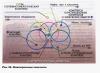
Rм = L/M S, where L is the average path length of the magnetic power lines, M is the magnetic permeability, and S is the cross-section of the magnetic circuit. When designing electromagnets, it is highly desirable to obtain a large power flux. This can be achieved by reducing the magnetic resistance. To do this, you need to select a magnetic core with the shortest path length of the power lines and the largest cross section, and the material should be an iron material with high magnetic permeability. Another way of increasing the power flow by increasing the ampere turns is not acceptable, since in order to save wire and power, one should strive to reduce the ampere turns. Usually, calculations of electromagnets are made according to special schedules. To simplify the calculations, we will also use some conclusions from the graphs. Suppose you need to determine the ampere turns and power flux of a closed iron magnetic circuit, shown in Figure 1a and made of the lowest quality iron.

Looking at the graph (unfortunately, I didn’t find it in the appendix) of the magnetization of iron, it is easy to see that the most advantageous magnetic induction is in the range from 10,000 to 14,000 lines of force per 1 cm2, which corresponds to from 2 to 7 ampere turns per 1 cm. For winding coils with the smallest number of turns and more economical in terms of power supply, for calculations it is necessary to take exactly this value (10,000 power lines per 1 cm2 at 2 ampere turns per 1 cm of length). In this case, the calculation can be made as follows. So, with the length of the magnetic circuit L = L1 + L2 equal to 20 cm + 10 cm = 30 cm, 2 × 30 = 60 ampere turns will be required.
If we take the diameter D of the core (Fig. 1, c) equal to 2 cm, then its area will be equal to: S = 3.14xD2/4 = 3.14 cm2. Here the excited magnetic flux will be equal to: Ф = B x S = 10000 x 3.14 = 31400 lines of force. The lifting force of the electromagnet (P) can also be approximately calculated. P = B2 S/25 1000000 = 12.4 kg. For a two-pole magnet this result should be doubled. Therefore, P = 24.8 kg = 25 kg. When determining the lifting force, it must be remembered that it depends not only on the length of the magnetic circuit, but also on the area of contact between the armature and the core. Therefore, the armature must fit exactly against the pole pieces, otherwise even the slightest air gaps will cause a strong reduction in lift. Next, the electromagnet coil is calculated. In our example, a lifting force of 25 kg is provided by 60 ampere turns. Let us consider by what means the product N J = 60 ampere turns can be obtained.
Obviously, this can be achieved either by using a high current with a small number of coil turns, for example 2 A and 30 turns, or by increasing the number of coil turns while reducing the current, for example 0.25 A and 240 turns. Thus, in order for an electromagnet to have a lifting force of 25 kg, 30 turns and 240 turns can be wound on its core, but at the same time change the value of the supply current. Of course, you can choose a different ratio. However, changing the current value within large limits is not always possible, since it will necessarily require changing the diameter of the wire used. Thus, during short-term operation (several minutes) for wires with a diameter of up to 1 mm, the permissible current density, at which the wire does not overheat, can be taken equal to 5 a/mm2. In our example, the wire should have the following cross-section: for a current of 2 a - 0.4 mm2, and for a current of 0.25 a - 0.05 mm2, the wire diameter will be 0.7 mm or 0.2 mm, respectively. Which of these wires should be wound? On the one hand, the choice of wire diameter can be determined by the available assortment of wire, on the other hand, by the capabilities of the power sources, both in terms of current and voltage. Indeed, two coils, one of which is made of thick wire of 0.7 mm and with a small number of turns - 30, and the other of which is made of wire of 0.2 mm and a number of turns of 240, will have sharply different resistance. Knowing the diameter of the wire and its length, you can easily determine the resistance. The length of the wire L is equal to the product of the total number of turns and the length of one of them (average): L = N x L1 where L1 is the length of one turn, equal to 3.14 x D. In our example, D = 2 cm, and L1 = 6, 3 cm. Therefore, for the first coil the length of the wire will be 30 x 6.3 = 190 cm, the resistance of the winding to direct current will be approximately equal to? 0.1 Ohm, and for the second - 240 x 6.3 = 1,512 cm, R? 8.7 Ohm. Using Ohm's law, it is easy to calculate the required voltage. So, to create a current of 2A in the windings, the required voltage is 0.2V, and for a current of 0.25A - 2.2V.
This is the elementary calculation of electromagnets. When designing electromagnets, it is necessary not only to make the indicated calculations, but also to be able to choose the material for the core, its shape, and think through the manufacturing technology. Satisfactory materials for making mug cores are bar iron (round and strip) and various. iron products: bolts, wire, nails, screws, etc. To avoid large losses on Foucault currents, cores for alternating current devices must be assembled from thin sheets of iron or wire isolated from each other. To make iron “soft,” it must be annealed. The correct choice of core shape is also of great importance. The most rational of them are ring and U-shaped. Some of the common cores are shown in Figure 1.
In this video lesson, the “E+M” channel talked about what an electromagnet is. He also showed how to make it by hand with a supply voltage of 12 volts and performed a series of experiments using it. Showed how to increase efficiency.
First, a little theory of history. In the early 19th century, Danish physicist Ørsted discovered the connection between electricity and magnetism. A current passing through a conductor located next to the compass deflects its needle towards the conductor. This indicates the presence of a magnetic field around the conductor. It also turned out that if you wind a conductor into a coil, its magnetic properties will increase. In a coil of wire, the so-called solenoid, magnetic lines are formed, the same as in a permanent magnet.


Depending on which side we carry the coil to the compass, it will deviate in one direction or another. Since two poles have formed in the coil: north and south. It is possible to change the direction of electric current when the poles are reversed. For the experiment, the author of the channel wound 2 identical coils. The first coil is 260 turns, resistance 7 ohms. 2 is twice as much. 520 turns, resistance 15 ohms. Power will be supplied from a DC source. Voltage 12 volts. In this case, it is a computer power supply. A lead-acid battery will also work.
Let's start experiments with the first coil, which has 260 turns. The multimeter is set to current measurement mode. It will show the current in amps flowing through the coil. As you can see, the indicator is 1.4 amperes. This is enough to attract small metal objects. Let's try a larger object. Let it be an iron ruble. The coil cannot handle this load. Let's try the same experiment with the second coil. The current here is 0.7 amperes. This is 2 times less than 1. At the same voltage of 12 volts. She also cannot attract the ruble. What can we do to increase the magnetic properties of our coil? Let's try to install an iron core. To do this we use a bolt. Now it will act as a magnetic circuit. The latter promotes the passage of magnetic flux through itself and increases the corresponding properties of the solenoid. Now our design has turned into an electromagnet. He can already handle the ruble with ease. The current remained the same, 1.4 amperes.
Let's experiment further and see how many of these objects a magnetic coil can attract.
The electromagnet heats up, which means its resistance increases. The higher the resistance, the lower the current. The less magnetic field the coil creates. Let's let the electromagnet cool completely and repeat the experiments. This time the load will be 12 coins. As you can see, the lower coins began to fall off on their own as the current decreased. No matter how much the presenter tried to experiment, he managed to raise no more than this load.
Let's carry out the same experiment with the second coil. It has twice as many turns. Let's see if it's stronger than the previous one.
Watch the continuation of the 12-volt electromagnet in the video from minute 6.
An electromagnet is a magnet that works (creates a magnetic field) only when electric current flows through a coil. To make a powerful electromagnet, you need to take a magnetic core and wrap it with copper wire and simply pass current through this wire. The magnetic core will begin to be magnetized by the coil and begin to attract iron objects. If you want a powerful magnet, increase the voltage and current, experiment. And so as not to have to worry about assembling the magnet yourself, you can simply remove the coil from the magnetic starter (they come in different types, 220V/380V). You take out this coil and insert a piece of any piece of iron inside (for example, an ordinary thick nail) and plug it into the network. This will be a really good magnet. And if you don’t have the opportunity to get a coil from a magnetic starter, then now let’s look at how to make an electromagnet yourself.
To assemble an electromagnet, you will need wire, a DC source, and a core. Now we take our core and wind copper wire around it (it’s better to turn one turn at a time, not in bulk - the efficiency will increase). If we want to make a powerful electromagnet, then we wind it in several layers, i.e. When you have wound the first layer, go to the second layer, and then wind the third layer. When winding, keep in mind that what you are winding, that coil has reactance, and when flowing through that coil, less current will flow with more reactance. But also keep in mind that we need and important current, because we will use current to magnetize the core, which serves as an electromagnet. But a large current will greatly heat the coil through which the current flows, so correlate these three concepts: coil resistance, current and temperature.

When winding the wire, select the optimal thickness of copper wire (about 0.5 mm). Or you can experiment, taking into account that the smaller the cross-section of the wire, the greater the reactance will be and, accordingly, the less current will flow. But if you wind with a thick wire (about 1mm), it would not be bad, because the thicker the conductor, the stronger the magnetic field around the conductor and, on top of that, more current will flow, because the reactance will be less. The current will also depend on the frequency of the voltage (if on alternating current). It’s also worth saying a few words about layers: the more layers, the greater the magnetic field of the coil and the stronger the core will magnetize, because When layers are superimposed, the magnetic fields add up.
Okay, the coil has been wound and the core has been inserted inside, now you can start applying voltage to the coil. Apply voltage and begin to increase it (if you have a power supply with voltage regulation, then gradually increase the voltage). At the same time, we make sure that our coil does not heat up. We select the voltage so that during operation the coil is slightly warm or just warm - this will be the nominal operating mode, and you can also find out the rated current and voltage by measuring on the coil and find out the power consumption of the electromagnet by multiplying the current and voltage.
If you are going to turn on an electromagnet from a 220-volt outlet, then first be sure to measure the resistance of the coil. When a current of 1 Ampere flows through the coil, the coil resistance should be 220 ohms. If 2 Amperes, then 110 Ohms. This is how we calculate CURRENT = voltage/resistance = 220/110 = 2 A.
That's it, turn on the device. Try holding a nail or a paper clip - it should attract. If it is poorly attracted or holds very poorly, then wind up five layers of copper wire: the magnetic field will increase and the resistance will increase, and if the resistance increases, then the nominal data of the electromagnet will change and it will be necessary to reconfigure it.
If you want to increase the power of the magnet, then take a horseshoe-shaped core and wind the wire on two sides, so you get a horseshoe lure consisting of a core and two coils. The magnetic fields of the two coils will add up, which means the magnet will work 2 times more powerful. The diameter and composition of the core plays a big role. With a small cross-section, we will get a weak electromagnet, even if we apply high voltage, but if we increase the cross-section of the heart, then we will get a not bad electromagnet. Yes, if the core is also made of an alloy of iron and cobalt (this alloy is characterized by good magnetic conductivity), then the conductivity will increase and due to this the core will be better magnetized by the field of the coil.