Rotation is a typical view mechanical movement, which is often found in nature and technology. Any rotation occurs as a result of the influence of some external force to the system under consideration. This force creates the so-called What it is, what it depends on, is discussed in the article.
Rotation process
Before considering the concept of torque, let us characterize the systems to which this concept can be applied. The rotation system assumes the presence of an axis around which it is carried out. Roundabout Circulation or turn. The distance from this axis to material points system is called the radius of rotation.
From a kinematics point of view, the process is characterized by three angular values:
- rotation angle θ (measured in radians);
- angular velocity ω (measured in radians per second);
- angular acceleration α (measured in radians per square second).
These quantities are related to each other by the following equalities:
Examples of rotation in nature are the movements of planets in their orbits and around their axes, and the movements of tornadoes. In everyday life and technology, the movement in question is typical for engine motors, wrenches, construction cranes, opening doors, and so on.
Determination of moment of force
Now let's move on to the immediate topic of the article. According to physical definition, represents vector product the vector of application of force relative to the axis of rotation to the vector of the force itself. The corresponding mathematical expression can be written as follows:
Here the vector r¯ is directed from the axis of rotation to the point of application of the force F¯.
In this formula for the torque M¯, the force F¯ can be directed in any way relative to the direction of the axis. However, a force component parallel to the axis will not produce rotation if the axis is rigidly fixed. In most problems in physics, one has to consider forces F¯, which lie in planes perpendicular to the axis of rotation. In these cases absolute value torque can be determined by the following formula:
|M¯| = |r¯|*|F¯|*sin(β).
Where β is the angle between the vectors r¯ and F¯.
What is leverage?
Lever of power plays important role when determining the magnitude of the moment of force. To understand what we're talking about, consider the following figure.

Shown here is a rod of length L, which is fixed at the point of rotation by one of its ends. The other end is acted upon by a force F directed under acute angleφ. According to the definition of moment of force, we can write:
M = F*L*sin(180 o -φ).
The angle (180 o -φ) appeared because the vector L¯ is directed from the fixed end to the free one. Considering the frequency trigonometric function sine, we can rewrite this equality as follows:
Now let's turn our attention to right triangle, built on the sides L, d and F. By the definition of the sine function, the product of the hypotenuse L and the sine of the angle φ gives the value of leg d. Then we come to equality:
Linear quantity d is called a lever of force. He equal to the distance from the force vector F¯ to the axis of rotation. As can be seen from the formula, the concept of a force lever is convenient to use when calculating the moment M. The resulting formula says that the maximum torque for a certain force F will occur only when the length of the radius vector r¯ (L¯ in the figure above) is equal to lever of force, that is, r¯ and F¯ will be mutually perpendicular.

Direction of action of the quantity M¯
It was shown above that torque is a vector characteristic for a given system. Where is this vector directed? Answering this question is not particularly difficult if we remember that the result of the product of two vectors is a third vector, which lies on the axis, perpendicular to the plane locations of the original vectors.
It remains to decide whether the moment of force will be directed upward or downward (toward or away from the reader) relative to the mentioned plane. This can be determined either by the gimlet rule, or using the rule right hand. Here are both rules:
- Right hand rule. If you position your right hand in such a way that its four fingers move from the beginning of the vector r¯ to its end, and then from the beginning of the vector F¯ to its end, then thumb, protruding, will indicate the direction of the moment M¯.
- The gimlet rule. If the direction of rotation of an imaginary gimlet coincides with the direction rotational movement systems, then forward movement The gimlet will point in the direction of the vector M¯. Remember that it only rotates clockwise.
Both rules are equal, so everyone can use the one that is more convenient for them.
When deciding practical problems different directions of torque (up - down, left - right) are taken into account using the signs "+" or "-". It should be remembered that the positive direction of the moment M¯ is considered to be one that leads to the rotation of the system counterclockwise. Accordingly, if some force leads to rotation of the system in the direction of the clock hand, then the moment it creates will have negative value.
Physical meaning of the quantity M¯
In the physics and mechanics of rotation, the value M¯ determines the ability of a force or a sum of forces to perform rotation. Since in mathematical definition The value of M¯ is not only the force, but also the radius vector of its application, then it is the latter that largely determines the noted rotational ability. To make it clearer what kind of ability we are talking about, here are a few examples:
- Every person, at least once in his life, tried to open a door, not by grasping the handle, but by pushing it close to the hinges. IN the latter case you have to make a significant effort to achieve the desired result.
- To unscrew the nut from a bolt, use special wrenches. The longer the wrench, the easier it is to unscrew the nut.
- To feel the importance of the lever of force, we invite readers to do the following experiment: take a chair and try to hold it suspended with one hand, in one case lean your hand against your body, in another - perform the task with a straight arm. The latter will be an impossible task for many, although the weight of the chair remains the same.

Torque units
A few words should also be said about the SI units in which torque is measured. According to the formula written down for it, it is measured in newtons per meter (N*m). However, these units also measure work and energy in physics (1 N*m = 1 joule). The joule for the moment M¯ does not apply, since work is a scalar quantity, while M¯ is a vector.
Nevertheless, the coincidence of units of moment of force with units of energy is not accidental. The work done to rotate the system, performed by the moment M, is calculated by the formula:
From this we find that M can also be expressed in joules per radian (J/rad).
Dynamics of rotation
At the beginning of the article we wrote down kinematic characteristics, which are used to describe the motion of rotation. In rotational dynamics, the main equation that uses these characteristics is the following:
The action of the moment M on a system having a moment of inertia I leads to the appearance angular acceleration α.

This formula used to determine angular frequencies of rotation in technology. For example, knowing the torque asynchronous motor, which depends on the frequency of the current in the stator coil and on the magnitude of the changing magnetic field, and also knowing the inertial properties of the rotating rotor, it is possible to determine to what rotation speed ω the engine rotor spins up in known time t.
Example of problem solution
The weightless lever, which is 2 meters long, has a support in the middle. What weight should be placed on one end of the lever so that it is in a state of equilibrium, if on the other side of the support at a distance of 0.5 meters from it lies a load weighing 10 kg?

Obviously, what will happen if the moments of force created by the loads are equal in magnitude. The force creating the moment in this problem is the weight of the body. The levers of force are equal to the distances from the loads to the support. Let us write the corresponding equality:
m 1 *g*d 1 = m 2 *g*d 2 =>
P 2 = m 2 *g = m 1 *g*d 1 /d 2 .
We obtain the weight P 2 if we substitute from the problem conditions the values m 1 = 10 kg, d 1 = 0.5 m, d 2 = 1 m. The written equality gives the answer: P 2 = 49.05 newton.
Definition 1
The moment of force is represented by a torque or rotational moment, being a vector physical quantity.
It is defined as the vector product of the force vector, as well as the radius vector, which is drawn from the axis of rotation to the point of application of the specified force.
The moment of force is a characteristic of the rotational effect of force on solid. The concepts of “rotating” and “torque” moments will not be considered identical, since in technology the concept of “rotating” moment is considered as an external force applied to an object.
At the same time, the concept of “torque” is considered in the format of internal force that arises in an object under the influence of certain applied loads (a similar concept is used for the resistance of materials).
Concept of moment of force
The moment of force in physics can be considered in the form of the so-called “rotational force”. The SI unit of measurement is the newton meter. The moment of a force may also be called the "moment of a couple of forces", as noted in Archimedes' work on levers.
Note 1
IN simple examples, when a force is applied to the lever in a perpendicular relation to it, the moment of force will be determined as the product of the magnitude of the specified force and the distance to the axis of rotation of the lever.
For example, a force of three newtons applied at a distance of two meters from the axis of rotation of the lever creates a moment equivalent to a force of one newton applied at a distance of 6 meters to the lever. More precisely, the moment of force of a particle is determined in the vector product format:
$\vec (M)=\vec(r)\vec(F)$, where:
- $\vec (F)$ represents the force acting on the particle,
- $\vec (r)$ is the radius of the particle vector.
In physics, energy should be understood as scalar quantity, while the moment of force will be considered a (pseudo) vector quantity. The coincidence of the dimensions of such quantities will not be accidental: a moment of force of 1 N m, which is applied through a whole revolution, making mechanical work, reports an energy of 2 $\pi$ joules. Mathematically it looks like this:
$E = M\theta$, where:
- $E$ represents energy;
- $M$ is considered to be the torque;
- $\theta$ will be the angle in radians.
Today, the measurement of moment of force is carried out by using special load sensors of strain gauge, optical and inductive types.
Formulas for calculating moment of force
An interesting thing in physics is the calculation of the moment of force in a field, produced according to the formula:
$\vec(M) = \vec(M_1)\vec(F)$, where:
- $\vec(M_1)$ is considered the lever moment;
- $\vec(F)$ represents the magnitude of the acting force.
The disadvantage of such a representation is the fact that it does not determine the direction of the moment of force, but only its magnitude. If the force is perpendicular to the vector $\vec(r)$, the moment of the lever will be equal to the distance from the center to the point of the applied force. In this case, the moment of force will be maximum:
$\vec(T)=\vec(r)\vec(F)$
When a force performs a certain action at any distance, it will perform mechanical work. In the same way, the moment of force (when performing an action through angular distance) will do the work.
$P = \vec (M)\omega $
In the existing international system measurements, power $P$ will be measured in Watts, and the moment of force itself will be measured in Newton meters. At the same time angular velocity is defined in radians per second.
Moment of several forces
Note 2
When a body is exposed to two equal and also oppositely directed forces, which do not lie on the same straight line, the absence of this body in a state of equilibrium is observed. This is explained by the fact that the resulting moment of the indicated forces relative to any of the axes does not have a zero value, since both represented forces have moments directed in the same direction (a pair of forces).
In a situation where the body is fixed on an axis, it will rotate under the influence of a couple of forces. If a couple of forces are applied in relation free body, in this case it will begin to rotate around an axis passing through the center of gravity of the body.
The moment of a pair of forces is considered to be the same with respect to any axis that is perpendicular to the plane of the pair. In this case, the total moment $M$ of the pair will always be equal to the product one of the forces $F$ by the distance $l$ between the forces (arm of the pair) regardless of the types of segments into which it divides the position of the axis.
$M=(FL_1+FL-2) = F(L_1+L_2)=FL$
In a situation where the resultant moment of several forces is equal to zero, it will be considered the same relative to all axes parallel to each other. For this reason, the effect on the body of all these forces can be replaced by the action of just one pair of forces with the same moment.
Electric motor power and torque
This chapter is devoted to torque: what it is, what it is needed for, etc. We will also look at the types of loads depending on the pump models and the correspondence between the electric motor and the pump load.
Have you ever tried to turn the shaft of an empty pump by hand? Now imagine turning it while the pump is filled with water. You will feel that in this case, much more force is required to create torque.
Now imagine that you have to turn the pump shaft for several hours in a row. You'd get tired faster if the pump was full of water, and you'd feel like you wasted a lot of money. more strength over the same period of time than when performing the same manipulations with an empty pump. Your observations are absolutely correct: more power is required, which is a measure of work (energy expended) per unit time. Typically, the power of a standard electric motor is expressed in kW.

Torque (T) is the product of force and force arm. In Europe it is measured in Newtons per meter (Nm).
As you can see from the formula, torque increases if force or leverage increases - or both. For example, if we apply a force of 10 N, equivalent to 1 kg, to a shaft with a lever length (force arm) of 1 m, the resulting torque will be 10 Nm. When the force increases to 20 N or 2 kg, the torque will be 20 Nm. In the same way, the torque would be 20 Nm if the lever was increased to 2 m and the force was 10 N. Or with a torque of 10 Nm with a force arm of 0.5 m, the force would be 20 N.

Work and power
Now let’s dwell on such a concept as “work”, which in in this context has special meaning. Work is done whenever a force—any force—causes motion. Work equals force times distance. For linear motion Power is expressed as work done at a certain point in time.
If we're talking about rotation, power is expressed as torque (T) multiplied by speed (w).
![]()
The rotational speed of an object is determined by measuring the time it takes for a certain point on a rotating object to complete a full rotation. Typically this value is expressed in revolutions per minute, i.e. min-1 or rpm. For example, if an object makes 10 full revolutions per minute, this means that its rotation speed is: 10 min-1 or 10 rpm.

So, rotation speed is measured in revolutions per minute, i.e. min-1.
Let's bring the units of measurement to a general form.

For clarity, let's take different electric motors to analyze in more detail the relationship between power, torque and speed. Although the torque and speed of electric motors vary greatly, they can have the same power.

For example, let's say we have a 2-pole motor (3000 rpm) and a 4-pole motor (1500 rpm). The power of both electric motors is 3.0 kW, but their torques are different.

Thus, the torque of a 4-pole motor is twice the torque of a 2-pole motor of the same power.
How are torque and speed generated?
Now that we've covered the basics of torque and speed, we need to look at how they are created.
In electric motors AC torque and speed are created as a result of the interaction between the rotor and the rotating magnetic field. The magnetic field around the rotor windings will tend to the magnetic field of the stator. In real operating conditions, the rotor speed always lags behind the magnetic field. Thus, the magnetic field of the rotor crosses the magnetic field of the stator and lags behind it and creates a torque. The difference in the rotational speed of the rotor and stator, which is measured in %, is called the sliding speed.

Slip is the main parameter of the electric motor, characterizing its operating mode and load. The greater the load that the electric motor must handle, the greater the slip.
Keeping in mind what was said above, let’s look at a few more formulas. The torque of an induction electric motor depends on the strength of the magnetic fields of the rotor and stator, as well as on the phase relationship between these fields. This relationship is shown in the following formula:
The strength of the magnetic field primarily depends on the design of the stator and the materials from which the stator is made. However, voltage and frequency also play an important role. The torque ratio is proportional to the square of the stress ratio, i.e. if the supplied voltage drops by 2%, the torque therefore decreases by 4%.

The rotor current is induced through the power supply to which the electric motor is connected, and the magnetic field is partially created by the voltage. The input power can be calculated if we know the details of the motor's power supply, i.e. voltage, power factor, current consumption and efficiency.

In Europe, shaft power is usually measured in kilowatts. In the US, shaft horsepower is measured in horsepower (hp).
If you need to convert horsepower to kilowatts, simply multiply the corresponding value (in horsepower) by 0.746. For example, 20 hp. equals (20 0.746) = 14.92 kW.
Conversely, kilowatts can be converted to horsepower by multiplying the kilowatt value by 1.341. This means that 15 kW equals 20.11 hp.
Motor torque
Power [kW or hp] relates torque to rotational speed to determine total volume work that must be completed in a certain period of time.
Let's look at the interaction between torque, power and speed, and how they relate to electrical voltage using the example of Grundfos electric motors. Electric motors have the same power rating at both 50 Hz and 60 Hz.

This entails sharp decline torque at 60 Hz: A frequency of 60 Hz causes a 20% increase in speed, which results in a 20% decrease in torque. Most manufacturers prefer to specify motor power at 60 Hz, so as line frequency drops to 50 Hz, motors will produce less shaft power and torque. Electric motors provide the same power at 50 and 60 Hz.
A graphical representation of the torque of the electric motor is shown in the figure.

The illustration represents a typical torque/speed characteristic. The following are terms used to describe the torque of an AC motor.
Starting torque(Mp): Mechanical torque developed by an electric motor on the shaft during startup, i.e. when current is passed through an electric motor at full voltage while the shaft is locked.
Minimum starting torque(Mmin): This term is used to indicate the lowest point on the torque/speed curve of an electric motor whose load is increased to full speed rotation. For most Grundfos electric motors, the minimum starting torque is not specified separately, since the most low point located at the point of the locked rotor. As a result, for most Grundfos motors the minimum starting torque is the same as the starting torque.
Locking torque(Mblock): Maximum torque is the torque produced by an AC motor at rated voltage, supplied at rated frequency, without sudden changes in rotational speed. It is called the ultimate overload torque or maximum torque.
Torque at full load(Mp.n.): Torque required to produce rated power at full load.
Pump Load and Motor Load Types
Highlight following types loads:
Constant power
The term "constant power" is used for certain types of loads that require less torque as the rotation speed increases, and vice versa. Constant power loads are typically used in metalworking applications such as drilling, rolling, etc.

Constant torque
As the name implies - “constant torque” - it is implied that the amount of torque required to operate a mechanism is constant, regardless of the speed of rotation. An example of such an operating mode is conveyors.

Variable torque and power
“Variable torque” - this category is of greatest interest to us. This torque is relevant for loads that require low torque at low speed and require higher torque as the speed increases. A typical example are centrifugal pumps.
All the rest this section will focus exclusively on variable torque and power.
Having determined that variable torque is typical for centrifugal pumps, we must analyze and evaluate some of the characteristics of a centrifugal pump. Using drives with variable frequency rotation is determined by special laws of physics. IN in this case This laws of similarity , which describe the relationship between pressure differences and flow rates.

Firstly, the pump flow is directly proportional to the rotation speed. This means that if the pump runs at 25% higher speed, the flow will increase by 25%.
Secondly, the pump pressure will change in proportion to the square of the change in rotation speed. If the rotation speed increases by 25%, the pressure increases by 56%.
Thirdly, what is especially interesting is that power is proportional to the cube of the change in rotation speed. This means that if the required speed is reduced by 50%, this equates to an 87.5% reduction in power consumption.
So, the laws of similarity explain why the use of variable speed drives is more appropriate in applications where variable values flow and pressure. Grundfos offers a range of electric motors with an integrated frequency converter that regulates the speed to achieve exactly this purpose.
Just like feed, pressure and power, the amount of torque required depends on the rotation speed.

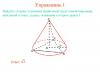
The figure shows a cross-section of a centrifugal pump. The torque requirements for this type of load are almost the opposite of those required for "constant power". For variable torque loads, the required torque at low speed is small, and the required torque at high frequency rotation - great. IN mathematical expression torque is proportional to the square of the rotation speed, and power is proportional to the cube of the rotation speed.

This can be illustrated using the torque/speed characteristic we used earlier when talking about motor torque:
As the motor accelerates from zero to rated speed, the torque can vary significantly. The amount of torque required at a given load also varies with speed. In order for an electric motor to be suitable for a given load, it is necessary that the torque of the electric motor always exceeds the torque required for a given load.

In the example, the centrifugal pump at rated load has a torque of 70 Nm, which corresponds to 22 kW at a rated speed of 3000 rpm. In this case, the pump requires 20% torque at rated load when starting, i.e. approximately 14 Nm. After starting, the torque drops slightly and then increases to full load as the pump picks up speed.
Obviously, we need a pump that will provide the required flow/pressure (Q/H) values. This means that the electric motor must not be allowed to stop, in addition, the electric motor must constantly accelerate until it reaches its rated speed. Therefore, it is necessary that the torque characteristic matches or exceeds the load characteristic over the entire range from 0% to 100% rotation speed. Any “excess” moment, i.e. The difference between the load curve and the motor curve is used as the rotation acceleration.
Matching the electric motor to the load
If you need to determine whether the torque of a particular motor meets the load requirements, you can compare the speed/torque characteristics of the motor with the speed/torque characteristics of the load. The torque produced by the motor must exceed the torque required by the load, including periods of acceleration and full speed.
Characteristics of the dependence of torque on the rotation speed of a standard electric motor and centrifugal pump.

If we look at the characteristic, we will see that when the electric motor accelerates, it starts at a current corresponding to 550% of the full load current.

As the motor approaches its rated speed, the current decreases. As one might expect, during initial period Start-up losses on the electric motor are high, so this period should not be long to prevent overheating.
It is very important that maximum speed rotation was achieved as accurately as possible. This is related to power consumption: for example, a 1% increase in rotation speed over the standard maximum results in a 3% increase in power consumption.
Power consumption is proportional to the diameter of the pump impeller to the fourth power.

Reducing the diameter of the pump impeller by 10% leads to a decrease in power consumption by (1- (0.9 * 0.9 * 0.9 * 0.9)) * 100 = 34%, which is equal to 66% of the rated power. This dependence is determined solely in practice, as it depends on the type of pump, the design of the impeller and how much you reduce the diameter of the impeller.
Motor start time
If we need to size an electric motor for a specific load, for example for centrifugal pumps, our main task is to provide the appropriate torque and power at the rated operating point, because the starting torque for centrifugal pumps is quite low. The starting time is quite limited, since the torque is quite high.

It is not uncommon for complex motor protection and control systems to take some time to start up so that they can measure the motor's starting current. The starting time of the electric motor and pump is calculated using the following formula:

tstart = time required for the pump motor to reach full load speed
n = motor speed at full load
Itotal = inertia, which requires acceleration, i.e. inertia of the electric motor shaft, rotor, pump shaft and impellers.
The moment of inertia for pumps and motors can be found in the relevant technical data.

Misb = excess torque accelerating rotation. The excess torque is equal to the motor torque minus the pump torque at various speeds.


As can be seen from the above calculations performed for this example with a 4 kW electric motor of a CR pump, the start time is 0.11 seconds.
Number of motor starts per hour
Modern complex systems Motor controls can control the number of starts per hour for each specific pump and motor. The need to control this parameter is that every time the electric motor is started and then accelerated, a high starting current consumption is noted. The starting current heats the electric motor. If the motor does not cool down, the continuous load from the inrush current will significantly heat the motor stator windings, resulting in motor failure or reduced insulation life.
Typically, the number of starts a motor can make per hour is the responsibility of the motor supplier. For example, Grundfos indicates maximum number starts per hour in the technical data for the pump, since maximum quantity starts depends on the moment of inertia of the pump.
Power and efficiency (eta) of the electric motor
There is a direct relationship between the power consumed by the electric motor from the network, the power on the electric motor shaft and the hydraulic power developed by the pump.
In the production of pumps, the following designations of these three are used: various types power.

P1 (kW) The electrical input power of the pumps is the power that the pump motor receives from the electrical power source. Power P! is equal to the power P2 divided by the efficiency of the electric motor.
P2 (kW) Motor shaft power is the power that the electric motor transmits to the pump shaft.
P3 (kW) Pump input power = P2, assuming that the coupling between the pump and motor shafts does not dissipate energy.
P4 (kW) Hydraulic power of the pump.
§ 92. Torque of an asynchronous motor
The torque of an asynchronous motor is created by the interaction of the rotating magnetic field of the stator with the currents in the conductors of the rotor winding. Therefore, the torque depends on both magnetic flux stator Φ, and on the current strength in the rotor winding I 2. However, only the active power consumed by the machine from the network is involved in creating torque. As a result, the torque does not depend on the current strength in the rotor winding I 2, but only from its active component, i.e. I 2 cos φ 2, where φ 2 is the phase angle between e. d.s. and current in the rotor winding.
Thus, the torque of an asynchronous motor is determined by the following expression:
M=CΦ Iφ 2 cos φ 2 , (122)
Where WITH- the design constant of the machine, depending on the number of its poles and phases, the number of turns of the stator winding, the design of the winding and the adopted system of units.
Provided that the applied voltage is constant and the motor load changes, the magnetic flux also remains almost constant.
Thus, in the expression for torque, the quantities WITH and Φ are constant and the torque is proportional only to the active component of the current in the rotor winding, i.e.
M ~ I 2 cos φ 2 . (123)
Changing the load or braking torque on the motor shaft, as is already known, changes both the rotor rotation speed and slip.
A change in slip causes a change in both the current in the rotor I 2 and its active component I 2 cos φ 2 .
The current strength in the rotor can be determined by the ratio e. d.s. to total resistance, i.e. based on Ohm's law
Where Z 2 , r 2 and x 2 - total, active and reactance of the rotor winding phase,
E 2 - e. d.s. phases of the winding of the rotating rotor.
Changing the slip changes the frequency of the rotor current. With a stationary rotor ( n 2 = 0 and S= 1) the rotating field crosses the conductors of the stator and rotor windings at the same speed and the frequency of the current in the rotor is equal to the frequency of the network current ( f 2 = f 1). As slip decreases, the rotor winding is crossed by a magnetic field with a lower frequency, as a result of which the frequency of the current in the rotor decreases. When the rotor rotates synchronously with the field ( n 2 = n 1 and S= 0), the conductors of the rotor winding are not crossed by the magnetic field, so the frequency of the current in the rotor is zero ( f 2 = 0). Thus, the frequency of the current in the rotor winding is proportional to slip, i.e.
f 2 = Sf 1 .
The active resistance of the rotor winding is almost independent of frequency, while e.g. d.s. and reactance are proportional to frequency, i.e. they change with slip and can be determined by the following expressions:
E 2 = S E And X 2 = S X,
Where E And X- uh. d.s. and the inductive reactance of the winding phase for a stationary rotor, respectively.
Thus we have:

and torque
Therefore, for small slips (up to approximately 20%), when the reactance X 2 = S X small compared to active r 2, an increase in slip causes an increase in torque, since this increases the active component of the current in the rotor ( I 2 cos φ 2). For large slips ( S X more than r 2) an increase in slip will cause a decrease in torque.
Thus, with increasing slip (its large values) although the current in the rotor increases I 2, but its active component I 2 cos φ 2 and, therefore, the torque decreases due to a significant increase reactance rotor windings.
In Fig. 115 shows the dependence of torque on slip. With some sliding S m(approximately 12 - 20%) the engine develops a maximum torque, which determines the overload capacity of the engine and is usually 2 - 3 times the rated torque.

Stable operation of the engine is possible only on the ascending branch of the torque-slip curve, i.e., when the slip changes from 0 to S m. Engine operation on the descending branch of the specified curve, i.e. when sliding S > S m, is impossible, since it is not provided here stable equilibrium moments.
If we assume that the torque was equal to the braking torque ( M vr = M torm) at points A And B, then if the balance of moments is accidentally disturbed, in one case it is restored, but in the other it is not restored.
Let's assume that the engine torque has decreased for some reason (for example, when the mains voltage drops), then the slip will begin to increase. If the moment equilibrium was at the point A, then an increase in slip will cause an increase in the engine torque and it will again become equal to the braking torque, i.e., the balance of moments will be restored with increased slip. If the moment equilibrium was at the point B, then an increase in slip will cause a decrease in torque, which will always remain less than the braking torque, i.e., the balance of moments will not be restored and the rotor speed will continuously decrease until the engine stops completely.
Thus, at the point A the machine will work stably, and at the point B stable operation is impossible.
If a braking torque greater than the maximum is applied to the motor shaft, the balance of moments will not be restored and the motor rotor will stop.
The torque of the motor is proportional to the square of the applied voltage, since both the magnetic flux and the current in the rotor are proportional to the voltage. Therefore, a change in network voltage causes a change in torque.
Electromagnetic moment.
Electromagnetic torque M Em occurs under the influence of forces acting on the rotor conductors, which are in a rotating magnetic field. Let us denote the instantaneous value of the rotor current by i 2 s (Fig. 3.16), magnetic induction at the same point through IN and the length of the conductor through l (rotor package length). Then the force acting on the conductor is f = IN l i 2 s
Induction IN and rotor current i 2 s in every at the moment time are distributed along the rotor circumference approximately according to a sinusoidal law, i.e.

The coordinate that determines the position of the conductor on the rotor (Fig. 3.16), and ψ 2 - phase shift angle between EMF e 2 s (according to clause 3.4.1 EMF e 2 s in phase with induction IN ) and rotor current i 2 s . Thus,
The average force acting on the conductor is defined as the integral along the rotor circumference of the force f
,
acting on one conductor:
Replacing the product of sines with the difference of cosines, we get:
 The integral of the second term, like the integral over two periods of the cosine function, equal to zero. Then

![]() Let us denote the number of rotor conductors by N
2
.
The force acting on all conductors will be F
=
N
2
f
Wed. Torque is the product of force F
by the radius of the rotor, i.e. M
=
FD
/2
.
Knowing that pole division is also for a sinusoid ,
we find the moment:
Let us denote the number of rotor conductors by N
2
.
The force acting on all conductors will be F
=
N
2
f
Wed. Torque is the product of force F
by the radius of the rotor, i.e. M
=
FD
/2
.
Knowing that pole division is also for a sinusoid ,
we find the moment:

 Let us denote the constant
![]() Then
Then
(3.20)  In this expression, where R
2
- active resistance, and X
2
s
-
inductive reactance of the rotating rotor phase. Formula (3.20) shows that the motor torque is created due to the interaction of magnetic flux and current in the rotor winding.
In this expression, where R
2
- active resistance, and X
2
s
-
inductive reactance of the rotating rotor phase. Formula (3.20) shows that the motor torque is created due to the interaction of magnetic flux and current in the rotor winding.
Sliding effect s and stator phase voltage per motor torque. In (3.20), the current value is determined from the expression where E 2 s And I 2 s - EMF and phase current of the rotating rotor;

Substituting values I 2s And cos Ψ 2 in (3.20), we get:

Considering that
then (3.21) can be rewritten: 
![]() Constant
Constant
Where w 2 - number of rotor turns; per stator phase (the number of phases is three).
Substituting the values into (3.22), we find: 
![]()
 Using the given values of the active and inductive resistances of the rotor phase, we obtain:

If we neglect the voltage drop in the stator winding, the formula takes the form 
The error in determining the torque when applying formula (3.22a) does not exceed 5%, which is quite acceptable for engineering problems. From (3.22a) it is clear that the torque is proportional to the square of the stator phase voltage. Change U 1 significantly affects the moment. So, if U 1 falls by 10%, then the torque drops by 19%.

![]() Formula (3.22a) can also be derived from the formula mechanical power engine:
Formula (3.22a) can also be derived from the formula mechanical power engine:
![]() Where m
- number of motor phases. Because ,
where is the angular velocity of the rotating field, then
Where m
- number of motor phases. Because ,
where is the angular velocity of the rotating field, then
Where ω 1 - angular frequency of current in the network.
 Taking into account formula (3.19) and denoting X
1
+
X
`
2
, we get:
Taking into account formula (3.19) and denoting X
1
+
X
`
2
, we get:
![]() 3.11.3.
Moment-slip characteristic
.
3.11.3.
Moment-slip characteristic
.
Moment-slip characteristic M
(
s
)
,
constructed according to (3.23) is shown in Fig. 3.17. Dot s
= 0, M
= 0 corresponds to ideal engine idle speed, and the point M
nom, s
nom- nominal mode. Plot HE
graphics - work area. In this area, dependence M
(
s
)
almost linear. Really slipping in this area s
= 0 + 0.08, therefore in formula (3.23) the value (X
To)
2
can be neglected. Then (3.23) takes the form ![]()
![]() where is a constant value for a given engine.
where is a constant value for a given engine.
Plot NK , The graphic corresponds to mechanical overload of the engine. At the point TO torque reaches maximum value and is called the critical moment. Slip s To, corresponding to the critical moment, is called critical slip.
 Plot OK
characteristics - section of statically stable engine operation (under stable work understands the ability of the engine to automatically compensate for small deviations in operating mode due to own characteristics). Let, for example, in steady state (M vr = M)
for some reason the moment of resistance will increase and become equal M'>M
.
Then a transient process will follow: rotor speed n
will decrease, slip s
will increase M vr according to specification M
(
s
)
will increase and the engine will reach a new steady state, characterized by a reduced rotation speed n
‘
and equality of moments M' time
= M'
.
Plot OK
characteristics - section of statically stable engine operation (under stable work understands the ability of the engine to automatically compensate for small deviations in operating mode due to own characteristics). Let, for example, in steady state (M vr = M)
for some reason the moment of resistance will increase and become equal M'>M
.
Then a transient process will follow: rotor speed n
will decrease, slip s
will increase M vr according to specification M
(
s
)
will increase and the engine will reach a new steady state, characterized by a reduced rotation speed n
‘
and equality of moments M' time
= M'
.
A statically stable section is characterized by a positive derivative dM / ds >0 . The value of the critical moment M To can be found from the condition dM / ds

. (3.24)
Equating (3.24) to zero, we obtain the value of the critical slip
Substituting s To in (3.23), we get
![]() (3.26)
(3.26)
Attitude M To / M nom =k m called multiplicity maximum torque. For serial engines k m=1,7/3,4 . .
Plot KP - area of unstable work. If for any reason M With there will be more M vr , then an analysis similar to that for a stable site shows that M vr will not increase, but, on the contrary, will decrease, which will lead to an increase in slip and an even greater decrease in torque - practically the engine rotor will stop instantly (Fig. 3.17, point P ). The area of unstable operation is characterized by a negative derivative: dM / ds <0.
At the point P slip s n=1 (n =0) .
On the site PT slip s > 1 . This is possible when the direction of rotation of the rotor is opposite to the direction of rotation of the field. Indeed, in this case s = n 1 — (- n )/ n 1 > 1 . Slip value s > 1 characterizes the braking mode of the engine, discussed in detail in § 3.16.
Expression of moment in o. e.(Kloss formula) To derive the torque formula in relative units Let us use expression (3.25), i.e. in (3.23) instead 3 P U 1 2 let's substitute its value 2ω 1 X k M k and take into account that R ‘ 2 = s k X k . As a result of the transformation, we obtain the Kloss formula:
 . (3.27)