DIFFRACTION GRATING, set large number regularly located elements (striations, slots, grooves, protrusions) on which light diffraction occurs. A diffraction grating is capable of decomposing the light incident on it into a spectrum, so it is used in spectral instruments as a dispersing element. Typically, the strokes are applied to a glass or metal, flat or concave surface. Strokes with a profile that is constant for a given grating are repeated after the same interval d, called the period of the diffraction grating. There are transmission and reflection diffraction gratings, which, depending on what changes - the amplitude or phase of the light wave, are divided into amplitude and phase. The simplest transmitting amplitude diffraction grating is a series of slits in an opaque screen (Figure 1, a), a reflective amplitude diffraction grating is a system of lines applied to a flat or concave mirror(Figure 1, b). The phase diffraction grating can take the form of a profiled glass plate (transmission diffraction grating, Figure 1, c) or a profiled mirror (reflective diffraction grating, Figure 1, d). Modern devices mainly use reflective phase diffraction gratings.
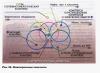
 When a monochromatic collimated beam of light with a wavelength λ falls at an angle α onto a diffraction grating with a period d (Figure 2), consisting of slits of width b separated by opaque spaces, interference of secondary waves emanating from different slits occurs. As a result, after focusing, intensity maxima are formed on the screen, the position of which is determined by the equation d(sin α + sin β) = mλ, where β is the angle between the normal to the diffraction grating and the direction of propagation of the diffraction beam (diffraction angle); m = 0, ±1, ±2, ±3, ... - the number of wavelengths by which a wave from a certain diffraction grating element lags behind a wave emanating from a neighboring grating element (or advances it). Monochromatic beams related to different meanings m are called the order of the spectrum, and the images of the entrance slit they create are called spectral lines M 1. All orders corresponding to positive and negative m are symmetrical with respect to zero. The more slits a diffraction grating has, the narrower and sharper the spectral lines. If white light falls on a diffraction grating, then for each wavelength a different set of spectral lines M 2, that is, the radiation will be decomposed into spectra according to the number possible values m. Relative intensity lines is determined by the energy distribution function from individual slits.
The main characteristics of a diffraction grating are angular dispersion and resolution. Angular dispersion dβ/dλ = m/dcos β characterizes the degree of angular separation of beams with different wavelengths. The resolving power R of a diffraction grating, which characterizes the minimum wavelength interval δλ that a given diffraction grating can separate, is determined by the expression R = λ/δλ = mN = Nd(sin α + sin β)/λ (N is the number of grating lines). At given angles the resolution can be increased only by increasing the width of the entire Nd diffraction grating. The dispersion region of the diffraction grating, that is, the value of the spectral interval Δλ in which the spectrum of a given order does not overlap with the spectra of neighboring orders, satisfies the relation Δλ = λ/m.
Diffraction gratings used to work in different areas spectrum, differ in size, shape, line profile, and frequency (from 6000 lines/mm in the X-ray region to 0.25 lines/mm in the infrared). According to the manufacturing method, diffraction gratings are divided into cut (original), replica (copies of original diffraction gratings) and holographic. Original cut diffraction gratings are produced using a special dividing machine with a diamond cutter, the profile of which determines the shape of the line. Making replicas consists of obtaining diffraction grating imprints on plastics and then applying a reflective metal layer to them. When producing a holographic diffraction grating on a photosensitive material, the interference of two coherent laser beams is recorded.
Diffraction gratings are used not only in spectrographs. They are used as selectively reflecting mirrors of lasers with tunable radiation frequencies, as well as in devices that provide compression of light pulses.
To manage settings laser radiation phase lattices are used, which are regular areas of compression and rarefaction in liquids or transparent solids, formed by exciting ultrasonic waves in them.
Lit.: Born M., Wolf E. Fundamentals of optics. 2nd ed. M., 1973; Lebedeva V.V. Experimental optics. 3rd ed. M., 1994; Akhmanov S. A., Nikitin S. Yu. Physical optics. 2nd ed. M., 2004; Sivukhin D.V. General course physics. 3rd ed. M., 2006. T. 4: Optics.
The diffraction grating device is based on the property of diffraction. A diffraction grating is a collection of very large quantity narrow slits that are separated by opaque spaces.
The general view of the diffraction grating is shown in the following figure.
Lattice period and principle of its operation
The grating period is the sum of the width of one slit and one opaque gap. The letter d is used for designation. The diffraction grating period often fluctuates around 10 µm. Let's look at how a diffraction grating works and why it is needed.
A plane monochromatic wave is incident on a diffraction grating. The length of this wave is equal to λ. Secondary sources located in the grating slits create light waves that will travel in all directions. We will look for conditions under which waves coming from different slits will reinforce each other.
To do this, consider the propagation of waves in any one direction. Let these be waves propagating at an angle φ.
The difference in path between the waves will be equal to the segment AC. If an integer number of wavelengths can be placed in this segment, then the waves from all the slits will overlap each other and reinforce each other.
The length Ac can be found from right triangle ABC.
AC = AB*sin(φ) = d*sin(φ).
We can write down the condition for the angle at which the maxima will be observed:
d*sin(φ) = ±k*λ.
Here k is any positive integer or 0. A value that determines the order of the spectrum.
A collecting lens is placed behind the grating. With its help, rays running parallel are focused. If the angle satisfies the maximum condition, then on the screen it determines the position of the main maxima. Since the position of the maxima will depend on the wavelength, the grating will decompose white light into a spectrum. This is shown in the following figure.
picture
picture
Between the maximum there will be intervals of minimum illumination. How larger number slots, the more clearly the maxima will be outlined, and the greater the width of the minima.
Diffraction grating is used for precise definition wavelength. With a known grating period, it is very easy to determine the wavelength; you just need to measure the direction angle φ to the maximum.
Diffraction of light – the phenomenon of light deviation from rectilinear propagation when meeting an obstacle, when light, bending around the obstacle, enters the region of its geometric shadow.
Jung's experience: There are two small holes in the opaque screen at a short distance from each other S 1 and S 2. These holes are illuminated by a narrow beam of light, which in turn passes through a small hole S on another screen. If there were no diffraction phenomenon, then we should only see a bright spot from the hole S on the second screen. In fact, a stable interference pattern is observed on the third screen (alternating light and dark stripes).
The phenomenon of diffraction can be explained on the basis Huygens-Fresnel principle.
According to Huygens, all points of the surface reached in at the moment wave, are the centers of secondary spherical waves. In this case, in a homogeneous medium, secondary waves are emitted only forward.
According to Fresnel, the wave surface at any time is the result of the interference of coherent secondary waves.
Explanation of Jung's experience
A spherical wave arising from a hole in accordance with the Huygens-Fresnel principle S excites in holes S 1 and S 2 coherent oscillations. Due to diffraction from holes S 1 and S 2, two light cones emerge that partially overlap and interfere. As a result of the interference of light waves, alternating light and dark stripes appear on the screen. When one of the holes is closed, the interference fringes disappear.
Diffraction is found in close proximity from an obstacle only if the size of the obstacle is commensurate with the wavelength (for visible lightλ ~ 100 nm).
Diffraction of light by a one-dimensional diffraction grating.
Diffraction grating– an optical device that is a collection of a large number of parallel, equally spaced slits of the same width. The number of strokes can reach up to 2000-3000 thousand per 1 mm. Transparent diffraction gratings made from a transparent solid, for example, plane-parallel glass or quartz plates. Strokes are applied with a diamond cutter. Where the cutter has passed, an opaque surface is formed that scatters light. The spaces between the strokes act as gaps. Reflective diffraction gratings They are a mirror (metal) surface on which parallel strokes are applied. The light wave is scattered by the streaks into separate coherent beams, which, having undergone diffraction by the streaks, interfere. The resulting interference pattern is formed in the reflected light.
If the width of the transparent slits (or reflective stripes) is equal to A, and the width of the opaque spaces (or light-scattering stripes) b, then the value
called period or constant diffraction grating.

Let us consider diffraction by a transparent diffraction grating. Let it fall on the bars plane monochromatic wave length l. To observe diffraction at close distances, a collecting lens is placed behind the grating and a screen behind it is placed on the focal length from the lens. Interference occurs at every point on the focal plane of the lens. N waves arriving at this point from N grate slits. This is the so-called multi-wave or multi-beam interference. Let us choose a certain direction of secondary waves at an angle φ relative to the normal to the grating. Rays coming from extreme points two adjacent slits have a path difference. The same path difference will be for secondary waves coming from other pairs of points of adjacent slits, separated by a distance d from each other. If this path difference is a multiple of an integer number of wavelengths, then interference will cause major highs:
–basic formula of diffraction grating,
Where k= 0, 1, 2… - the order of the main maxima. Narrow single-color lines are observed on the screen (depending on the color of the incident wave). Line at an angle φ = 0 is called the first order spectral line ( k= 0) on both sides of it there are symmetrically located spectral lines of the first order ( k = 1, k= -1), second order ( k = 2, k= -2), etc. The intensity of these lines in N 2 times the intensity produced in the φ direction by a single slit. With growth k spectral lines become less bright and cease to be observed altogether. The maximum observed number of lines is limited for the following reasons. Firstly, as the angle increases φ the intensity of light emitted by an individual slit decreases. Secondly, even very narrow slots with a width close to λ , cannot deflect light at an angle greater than. That's why, . Increasing the number of slits does not change the position of the main maxima, but makes them more intense. With oblique incidence of light at an angle , the condition for the main maxima has the form: .

Between the main maxima appear additional minimums, the number of which is equal N– 1, where N – total number grate slits. (In the figure on the left for N= 8 and N= 16 not all additional minima are drawn). They appear due to mutual compensation of waves from all N cracks. To N waves canceled each other out, the phase difference should differ by. And the optical path difference, accordingly, should be equal. The directions of additional minima are determined by the condition where k accepts integer values other than 0, N, 2N, 3N,..., that is, those under which this condition turns into basic formula diffraction grating.
Between the additional minima there is N – 2 additional highs, the intensity of which is very weak.
Under normal illumination of the grating with white light, a white central maximum of zero order is observed on the screen, and on both sides of it - diffraction spectra 1st, 2nd, etc. orders of magnitude. The spectra have the appearance of rainbow stripes, in which there is a continuous transition from purple at the inner edge of the spectrum to red at the outer edge.
From the spectra of the 2nd and 3rd orders, their partial overlap begins (since the condition is met).
The spectroscopic characteristics of the grating are: resolution and angular dispersion.
Diffraction grating resolution– dimensionless quantity, where is the minimum difference between the waves of two spectral lines at which these lines are perceived separately, λ is the average value of the wavelengths of these lines. It can be proven that where L– width of the diffraction grating.
Angular dispersion characterizes the degree of spatial (angular) separation of light rays with different wavelengths: , where φ – angular distance between spectral lines differing in wavelength by . It's easy to prove that.
Thus, the grating is a spectral device that can be used in various optical instruments, for example, in diffraction spectrophotometers, as monochromators, i.e. devices that allow illuminating an object with light in a narrow range of wavelengths.
A diffraction grating can be used to determine the wavelength of light (using the basic diffraction grating formula). On the other hand, the basic diffraction grating formula can be used to solve the inverse problem - finding the diffraction grating constant along the wavelength. This method formed the basis of X-ray diffraction analysis - measuring crystal lattice parameters by diffraction x-rays. Currently, X-ray diffraction analysis of biological molecules and systems is widely used. It was by this method that J. Watson and F. Crick established the structure of the DNA molecule (double helix) and were awarded the Nobel Prize in 1962.
DEFINITION
Diffraction grating- this is the simplest spectral device, consisting of a system of slits (areas transparent to light) and opaque gaps that are comparable to the wavelength.
One-dimensional diffraction grating, consists of parallel slits of the same width, which lie in the same plane, separated by equal-width spaces opaque to light. Reflective diffraction gratings are considered the best. They consist of a set of areas that reflect light and areas that scatter light. These gratings are polished metal plates onto which light-scattering strokes are applied with a cutter.
The diffraction pattern on a grating is the result of mutual interference of waves coming from all slits. Using a diffraction grating, multi-beam interference of coherent beams of light that have undergone diffraction and coming from all slits is realized.
A characteristic of a diffraction grating is its period. The period of the diffraction grating (d) (its constant) is a value equal to:
where a is the slot width; b is the width of the opaque area.
Diffraction by a one-dimensional diffraction grating
Let us assume that the light falls perpendicular to the plane of the diffraction grating. light wave with length . Since the slots in the grille are located on equal distances from each other, then the differences in the path of the rays () coming from two adjacent slits for the direction will be the same for the entire diffraction grating under consideration:
The main intensity minima are observed in the directions determined by the condition:
In addition to the main minima, as a result of mutual interference of light rays that come from two slits, the rays cancel each other out in some directions. As a result, additional intensity minima arise. They appear in those directions where the difference in the path of the rays is odd number half-wave The condition for additional minima is the formula:
where N is the number of slits of the diffraction grating; — integer values other than 0. If the grating has N slits, then between the two main maxima there is an additional minimum that separates the secondary maxima.
The condition for the main maxima for a diffraction grating is:
The value of the sine cannot be greater than one, then the number of main maxima is:

Examples of solving problems on the topic “Diffraction grating”
EXAMPLE 1
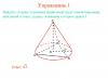
| Exercise | A monochromatic beam of light with wavelength θ is incident on a diffraction grating, perpendicular to its surface. The diffraction pattern is projected onto a flat screen using a lens. The distance between two first-order intensity maxima is l. What is the diffraction grating constant if the lens is placed in close proximity to the grating and the distance from it to the screen is L. Consider that |
| Solution | As a basis for solving the problem, we use a formula that relates the constant of the diffraction grating, the wavelength of light and the angle of deflection of the rays, which corresponds to the diffraction maximum number m: According to the conditions of the problem, since the angle of deflection of the rays can be considered small (), we assume that: From Fig. 1 it follows that:
Let's substitute expression (1.3) into formula (1.1) and take into account that , we get:
From (1.4) we express the lattice period: |
| Answer |


EXAMPLE 2
| Exercise | Using the conditions of Example 1 and the result of the solution, find the number of maxima that the lattice in question will give. |
| Solution | In order to determine the maximum angle of deflection of light rays in our problem, we will find the number of maxima that our diffraction grating can give. To do this we use the formula: where we assume that for . Then we get: |
It is no secret that, along with tangible matter, we are also surrounded by wave fields with their own processes and laws. These can be electromagnetic, sound, and light vibrations, which are inextricably linked with visible world, interact with it and influence it. Such processes and influences have long been studied by various scientists, who have derived basic laws that are still relevant today. One of the widely used forms of interaction between matter and waves is diffraction, the study of which led to the emergence of such a device as a diffraction grating, which is widely used in instruments for further research wave radiation, and in everyday life.
Concept of diffraction
Diffraction is the process of light, sound and other waves bending around any obstacle encountered along their path. More generally, this term can be called any deviation of wave propagation from the laws geometric optics, occurring near obstacles. Due to the phenomenon of diffraction, waves fall into the region of a geometric shadow, go around obstacles, penetrate through small holes in screens, etc. For example, you can clearly hear a sound when you are around the corner of a house, as a result of the sound wave going around it. Diffraction of light rays manifests itself in the fact that the shadow area does not correspond to the passage opening or existing obstacle. The operating principle of a diffraction grating is based on this phenomenon. Therefore, the study of these concepts is inseparable from each other.
Concept of a diffraction grating
A diffraction grating is an optical product that represents periodic structure, consisting of a large number of very narrow slits separated by opaque spaces.

Another version of this device is a set of parallel microscopic strokes having same shape, deposited on a concave or flat optical surface with the same at a given step. When light waves fall on the grating, a process of redistribution of the wave front in space occurs, which is due to the phenomenon of diffraction. That is, white light is decomposed into individual waves having different lengths, which depends on spectral characteristics diffraction grating. Most often, to work with the visible range of the spectrum (with a wavelength of 390-780 nm), devices with from 300 to 1600 lines per millimeter are used. In practice, the grating looks like a flat glass or metal surface with rough grooves (strokes) applied at certain intervals that do not transmit light. With the help of glass gratings, observations are carried out both in transmitted and reflected light, with metal gratings - only in reflected light.
Types of gratings
As already mentioned, according to the material used in manufacturing and the features of use, diffraction gratings are divided into reflective and transparent. The first include devices that are made of metal mirror surface with applied strokes, which are used for observations in reflected light. In transparent gratings, strokes are applied to a special optical surface that transmits rays (flat or concave), or narrow slits are cut in an opaque material. Studies when using such devices are carried out in transmitted light. An example of a coarse diffraction grating in nature is eyelashes. Looking through squinted eyelids, you can at some point see spectral lines.

Operating principle
The operation of a diffraction grating is based on the phenomenon of diffraction of a light wave, which, passing through a system of transparent and opaque areas, is divided into separate beams coherent light. They undergo diffraction by the lines. And at the same time they interfere with each other. Each wavelength has its own diffraction angle, so decomposition occurs white light into the spectrum.
Diffraction grating resolution
Being an optical device used in spectral instruments, it has a number of characteristics that determine its use. One of these properties is resolution, which consists in the possibility of separately observing two spectral lines with close wavelengths. Increasing this characteristic is achieved by increasing total number lines present in the diffraction grating.

IN good device the number of strokes per millimeter reaches 500, that is, with total length For a 100-mm grating, the total number of lines will be 50,000. This figure will help achieve narrower interference maxima, which will make it possible to highlight close spectral lines.
Application of diffraction gratings
Using this optical device, it is possible to accurately determine the wavelength, so it is used as a dispersing element in spectral devices for various purposes. A diffraction grating is used to isolate monochromatic light(in monochromators, spectrophotometers and others), as an optical sensor of linear or angular displacements (the so-called measuring grating), in polarizers and optical filters, as a beam splitter in an interferometer, as well as in anti-glare glasses.

In everyday life, you can often come across examples of diffraction gratings. The simplest of reflective devices can be considered the cutting of compact discs, since a track is applied to their surface in a spiral with a pitch of 1.6 microns between turns. A third of the width (0.5 microns) of such a track falls on the recess (where the recorded information is contained), which scatters the incident light, and about two thirds (1.1 microns) is occupied by an untouched substrate capable of reflecting the rays. Therefore, a CD is a reflective diffraction grating with a period of 1.6 µm. Another example of such a device is holograms various types and directions of application.
Manufacturing
To obtain a high-quality diffraction grating, it is necessary to maintain very high manufacturing accuracy. An error when applying even one stroke or gap leads to immediate rejection of the product. For the manufacturing process, a special dividing machine with diamond cutters is used, attached to a special massive foundation. Before starting the grating cutting process, this equipment must run for 5 to 20 hours in idle mode in order to stabilize all components. Manufacturing one diffraction grating takes almost 7 days. Despite the fact that each stroke takes only 3 seconds to apply. When manufactured in this way, the gratings have parallel strokes equally spaced from each other, the cross-sectional shape of which depends on the profile of the diamond cutter.
Modern diffraction gratings for spectral instruments
Currently widespread new technology their production by creating an interference pattern obtained from laser radiation on special light-sensitive materials called photoresists. As a result, products with a holographic effect are produced. You can apply strokes in this way on a flat surface, obtaining a flat diffraction grating or a concave spherical one, which will give a concave device that has a focusing effect. In the design of modern spectral devices both apply.

Thus, the phenomenon of diffraction is common in everyday life everywhere. This determines the widespread use of such based this process devices like diffraction gratings. It can either become part of research equipment or be found in everyday life, for example, as the basis for holographic products.