Differential equation in symbolic form
Differential equation in classical form
Homogeneous differential equation
Characteristic equation
Characteristic polynomial

Transfer function

Roots characteristic equation:

General solution to a differential equation


Since the roots are complex and pairwise conjugate, the nature of the transition process is non-monotonic (oscillatory).
The roots of the characteristic equation are in the left half-plane. The system is stable.
The frequency transfer function, or complex gain W(j), can be entered in two ways:
1. By finding the response to a sinusoidal (harmonic signal).
2. Using the Fourier transform.
Let's start with the first method and find the response of system (2.2.1) to a harmonic signal, which we will present in exponential form
where Xm and are the amplitude and circular frequency.
Since in linear system there are no nonlinear distortions, then in steady state the output will also have a harmonic signal of the same frequency, in general case with different amplitude and phase, i.e.
To determine the amplitude and phase, we substitute the expressions of the signals (2.4.11), (2.4.12) and their derivatives into the differential equation and after reduction by ejt 0 and elementary transformations we get the identity

These relationships can be considered as a definition of the frequency transfer function. They contain physical meaning frequency transfer function and from them follows a method for its experimental determination by measuring the amplitudes of harmonic signals at the input and output and the phase shift between them for the same frequency.
In the case of the second method of determining the frequency transfer function, compare (2.4.13) and (2.2.15). From the comparison it follows that the frequency transfer function is a special case of the Laplace transfer function for p = j, i.e.

Since the Laplace transfer function is applicable to signals of arbitrary (any) shape, the frequency transfer function is also applicable to find the response to a signal free form, and not necessarily harmonic. From (2.4.5) for the Fourier image of the reaction we have
The reaction itself, that is, the original, is found according to the inversion formula

Thus, from the second definition of the frequency transfer function, the frequency method (Fourier transform method) for finding the reaction follows:
1. For a given input signal, find the image using Fourier

2. Find the Fourier image of the reaction using (2.4.16)
Y(j) = X(j)W(j). (2.4.20)
3. According to the inversion formula ( inverse conversion Fourier) we find the reaction

The nature of the transformation of the input signal by a link or system is determined by the frequency transfer function or the corresponding frequency characteristics. Types of frequency characteristics are closely related to recording forms complex numbers, since for the frequency transfer function is a complex number.
Main frequency characteristics (Fig. 2.4.3-2.4.6).
1. Amplitude-phase characteristic (APC) - dependence of W(j) on complex plane when changing from - to + (Fig. 2.4.3). Since Wх() = Wх(-) - even function, and Wу() = Wу(-) - odd function, then AFC for< 0 симметрична относительно вещественной оси характеристике для >0 and is not usually depicted.

2. Real Wх() and imaginary Wу() frequency characteristics (Fig. 2.4.4) - dependences of the real and imaginary parts on frequency. Bearing in mind the parity of the real characteristic and the oddness of the imaginary one, for them< 0 обычно не изображают. Четность Wх() и нечетность Wу() вытекают из правила (2.4.22) их выделения из W(j), так как в знаменателе четная функция, а в числителе j в четной степени - действительное число (отходит к Wх()), а в нечетной -мнимое (отходит к Wy()).
3. Amplitude (AFC) and phase (PFC) frequency characteristics - dependences of A() and () on frequency (Fig. 2.4.5). Due to the evenness of A() and the oddness of (), they are for< 0 обычно не изображают. Амплитудная частотная характеристика определяет инерционность (пропускную способность) звена или системы. Фазовая частотная характеристика определяет величину фазового сдвига на соответствующей круговой частоте.
4. Inverse frequency response W-1(j) = 1/ W(j). Determining the amplitude and argument (phase) for the fraction according to rule (2.4.6), we find
From the connection between the forms of writing complex numbers it follows that from the AFC it is possible to construct Wх(), Wу() or А(), (), as well as W-1(j) and vice versa. Figure 2.4.6 shows the inverse characteristic for the characteristic in Figure 2.4.3. The figure shows a circle of unit radius. In accordance with rule (2.4.22), the points corresponding to A() > 1 lie inside a circle of unit radius. Point A() = 1 remains on the circle, but the phase changes to the opposite (by 180).

However, links are considered for which the condition of physical feasibility is not satisfied. This is valid in a certain frequency range. If the spectrum of the signal at the input of the link falls outside this range, then distortions in the response will occur that are not provided for by the transfer function of the link.
5. Logarithmic frequency characteristics.
The most widely used are logarithmic characteristics. To explain them, let us present the frequency transfer function in exponential form and take natural logarithm from:
It is equal complex expression; its real part is the logarithm of the module, and its imaginary part is the phase.
In practice it is taken decimal logarithm, so that the logarithmic amplitude (LAH) and phase (LPH) characteristics are determined by the expressions:

The abscissa axis in the graphs shows the frequency in logarithmic scale, i.e. lg. However, it is advisable to do digitization directly in circular frequency values, and for marking you can use Table 2.4.1. Values
Table 2.4.1
Amplitude is measured in decibels, phase - in degrees. To mark the x-axis directly in values (rad/s), you can use any of the three scales (basic, quadratic and cubic) slide rule(Fig.2.4.7).

If we take D mm as a decade, then, for example, 0.301 deca (corresponding to = 2 rad/s) will be 0.301D mm, 1.301 deca (corresponding to 20 rad/s) will be D+0.301D mm, etc. Thus, points with digitization in the range from 1 to 10 are shifted to the right by a decade and digitized from 10 to 100, etc. (Fig. 2.4.7), shift to the left from the original position by one decade and digitize from 0.1 to 1, etc.
If 2 /1 = 10, then the distance between frequencies is equal to one decade (log10 = 1), if 2 /1 = 2, then the distance is equal to one octave.
Since log(= 0) = -, then the point = 0 is at infinity to the left. Therefore, the ordinate axis is drawn anywhere so that the frequency range of interest falls on the graph. Since 20lg1 = 0, then L() > 0 if A()>1 and L()< 0, если А() < 1. Если А() 0, то L() -.
Let us consider the LAC of the inertial link. We have
A() = ; . (2.4.24)
To the left of the coupling frequency 0, i.e. in the case of 0, we neglect the sign of the radical of magnitude 2 compared to 02. Then
L() 20lg(k). (2.4.25)
Consequently, to the left of 0 the asymptotic LAX is a horizontal straight line at a height of 20lg(k). If k = 1, then this straight line coincides with the frequency axis.
To the right of the conjugate frequency 0, where 0, we similarly obtain a straight line with a slope of -20 dB/dec, since log is plotted along the abscissa axis.
L() 20lg(k) - 20lg, (2.4.26)
At point 0 we have an error in replacing the exact (real) characteristic with an asymptotic one, equal to

Lacc(0)=Lacc(0)+L(0),
That real characteristic at point 0 is located below the asymptotic one by 3 dB. In practice, an error of 3 dB is considered small and is not taken into account.
Logarithmic characteristics of links
Table 2.4.6

From Table 2.4.6 it follows:
1. The slope and, accordingly, the phase shift at low frequencies can only be provided by integrating or differentiating links. If, for example, there are r integrating links in the transfer function, then the slope of the LAC at low frequencies is equal, and the phase shift is correspondingly equal.
2. n roots of the denominator (poles of the transfer function), i.e. degree of the denominator n, corresponds to the slope of the LAC at high frequencies, equal to, and in the case of a minimum phase system - accordingly, a phase shift of high frequencies ah, equals.
3. The roots of the numerator (zeros of the transfer function) at high frequencies similarly correspond to the slope of the LAC, equal to, and the phase shift.
4. In the case of a transfer function

minimum-phase system with n poles and n1 zeros, the slope of the LAC at high frequencies is equal, and the phase shift is equal to degrees.
Construction of logarithmic characteristics of systems
and restoration of the transfer function according to LAX
If the links of the system are connected in series, then
and for the module and argument of the complex gain of the open-loop system, respectively, we have:
Obviously,
Consequently, to construct the LAC and LFC, it is necessary to sum up the corresponding characteristics of individual links.
Example 2.4.3. Construct LAC and LFC using the transfer function

Where; With; With. Accordingly, the coupling frequencies are equal; ;.
Let us represent the transfer function as a product of the transfer functions of the integrating link
inertial links

and forcing
Logarithmic amplitude and phase characteristics individual links, as well as the resulting LAC and LFC systems are plotted in Fig. 2.4.13 and 2.4.14.
In Fig. 2.4.13, thick lines show the asymptotic LAC of the links. The characteristics of the two inertial links with the transfer functions and on the graphs merge, but they must be taken into account twice. This also applies to the physical management of these units. To construct the resulting LAC, the characteristics of the remaining links were sequentially added to the LAC of the integrating link when moving along the frequency axis from left to right as the conjugate frequencies met. After the next coupling frequency, the slope of the LAC changed to. The slope increment corresponded to the link to which the mating frequency belonged.
Analyzing the results of the example and the characteristics of typical links (Table 2.4.6), we can conclude that the LAC of an open-loop system can be constructed immediately, bypassing the intermediate construction of the LAC of links and their summation, according to the rule:
1. Find the conjugate frequencies and plot them on the frequency axis. For convenience, draw the y-axis to the left of the lowest conjugate frequency.
2. At u = 1, set aside 20 logk and through this point draw a straight line with a slope of -20 dB/dec, if the system has integrating links, or with a slope of +20 dB/dec, if the system has differentiating links (at = 0 low-frequency the LAX asymptote is parallel to the x-axis).
3. When passing from left to right of each of the coupling frequencies, the characteristic experiences a slope increment of -20 dB/dec (for the inertial link), -40 dB/dec (for the oscillating link), +20 dB/dec (for the forcing link), +40 dB /dec (for the link opposite to the oscillatory one). If the coupling frequencies of several links are the same, then the increment in the slope of the LAC is equal to the total increment from all links. If there is at least one conjugation frequency less than unity, then the point 20lgk at u = 1 will not lie on the resulting LAC.
4. Introduce a correction to the asymptotic LAC in the presence of oscillatory or inverse links.
To control the correctness of the construction of the LAC and LFC, it is useful to remember that the slope of the LAC in the high frequency region (n > ?) is equal to 20 (m-n) dB/dec, where m is the order of the numerator, n is the order of the denominator of the system transfer function. Besides
where the minus sign is taken in the presence of integrating links, and the plus sign is taken in the presence of differentiating links. From the analysis of the methodology for constructing the LAC from the transfer function, the possibility of a reverse transition follows, i.e., restoring the transfer function of the minimum-phase system from the LAC.
When restoring the transfer function of a minimum-phase system according to the LAC, we write down a fraction, in the numerator of which we put overall coefficient strengthening and then we make the filling of the fraction. Based on the slope of the low-frequency section, we determine the number of integrating or differentiating links (formally, a negative slope corresponds to integrating links and, accordingly, a multiplier in the denominator, a positive slope corresponds to a multiplier in the numerator, and the slope factor is 20 decibels). In the case of zero slope, there are no integrating or differentiating links. Next, moving from left to right as the conjugation frequencies meet, we analyze the increment (change) of the slope. If the increment is +20 dB/dec, then we write in the numerator for the forcing link of the type, if the increment is -20 dB/dec, then we write in the denominator for the inertial link of the type. In the case of a slope increment of +40 dB/dec, we write two forcing links in the numerator; in the case of a slope increment of -20 dB/dec, we write two inertial links of the form in the denominator. If the LAX shows a correction for the damping coefficient, then instead of two forcing or inertial links we write the inverse of the oscillatory or oscillatory link (a multiplier in the numerator or denominator). If the tilt ratio is 3 or more, then we write down the corresponding number of links with the same conjugation frequencies. To determine the gain, we find the point of intersection of the continuation of the low-frequency section of the LAC with the vertical straight line with the abscissa and determine it using the ordinate of this point.
In the case of a minimum-phase system in the binomials and trinomials mentioned above, we take the “+” signs. If there were non-minimum-phase links, then it would be necessary to take the “-“ sign. In this case, the LAH would remain the same, and the LPH would be different. Therefore, in the case of a minimum-phase system, the recovery is unambiguous and there is no need to control the AFC.
Example 2.4.4. Restore the transfer function of the minimum-phase system according to the LAC Fig. 2.4.15.

Fig.2.4.15.
In accordance with the above considerations, the transfer function of the minimum-phase system will be equal to

Using the RLC circuit of task 1, write down the frequency transfer function and analytical expressions frequency characteristics.
5. Construct the amplitude-phase characteristic (APC).
6. Construct amplitude and phase frequency characteristics.
7. Construct real and imaginary frequency characteristics.
8. Construct logarithmic characteristics (LAX and LFC). Determine what type of corrective links this link belongs to (integrating, differentiating, integro-differentiating). What frequencies is this filter?
9. Using the AFC, construct the inverse frequency response.
Frequency transfer function in parametric form

Amplitude frequency response
Phase frequency response
Real frequency response
The free mode of the circuit does not depend on energy sources, it is determined only by the structure of the circuit and the parameters of its elements. It follows from this that the roots of the characteristic equation p1, p2,…, pn will be the same for all variable functions(currents and voltages).
Characteristic equation can be made various methods. The first method is classical, when the characteristic equation is compiled strictly in accordance with the differential equation classic scheme. When calculating transient processes in a complex circuit, a system of “m” differential equations is compiled according to Kirchhoff’s laws for the circuit diagram after switching. Since the roots of the characteristic equation are common to all variables, then the solution to the system differential equations performed relative to any variable (optional). As a result of the solution, an inhomogeneous differential equation with one variable is obtained. Compose a characteristic equation in accordance with the resulting differential equation and determine its roots.
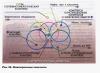
Example. Draw up a characteristic equation and determine its roots for the variables in the diagram in Fig. 59.1. The parameters of the elements are specified in a general form.

System of differential equations according to Kirchhoff's laws:

Let us solve the system of equations for the variable i 3, as a result we obtain a non-homogeneous differential equation:

The second way to compile a characteristic equation is to equate to zero the main determinant of the Kirchhoff system of equations for the free component variables.
Let the free component of an arbitrary current have the form i ksw = A k e pt , then:

The system of equations for the free components is obtained from the Kirchhoff system of differential equations by replacing the derivatives of the variables by the factor p, and the integrals by 1/p. For the example under consideration, the system of equations for free components has the form:

Characteristic equation and its root:

The third way to compile a characteristic equation (engineering) is to equate the input operator resistance of the circuit to zero relative to any of its branches.
The operator resistance of an element is obtained from its complex resistance by simply replacing the factor jω with p, therefore
For the example in question:

The third method is the simplest and most economical, therefore it is most often used when calculating transient processes in electrical circuits.
The roots of the characteristic equation characterize the free transient process in a circuit without energy sources. This process occurs with energy losses and therefore decays over time. It follows from this that the roots of the characteristic equation must be negative or have a negative real part.
In the general case, the order of the differential equation that describes the transient process in the circuit, and, consequently, the degree of the characteristic equation and the number of its roots are equal to the number of independent initial conditions, or the number of independent energy storage devices (coils L and capacitors C). If the circuit diagram contains parallel-connected capacitors C1, C2,... or series-connected coils L1, L2,..., then when calculating transient processes they must be replaced by one equivalent element C E = C1 + C2+... or L E = L1 + L2+…
Thus, general view solutions for any variable when calculating a transient process can be compiled only from an analysis of the circuit diagram, without compiling and solving a system of differential equations.
For the example discussed above.
Matrix representation of a system of ordinary differential equations (SODE) with constant coefficients
Linear homogeneous SODE with constant coefficients $\left\(\begin(array)(c) (\frac(dy_(1) )(dx) =a_(11) \cdot y_(1) +a_(12) \cdot y_ (2) +\ldots +a_(1n) \cdot y_(n) \\ (\frac(dy_(2) )(dx) =a_(21) \cdot y_(1) +a_(22) \cdot y_(2) +\ldots +a_(2n) \cdot y_(n) \\ (\ldots ) \\ (\frac(dy_(n) )(dx) =a_(n1) \cdot y_(1) +a_(n2) \cdot y_(2) +\ldots +a_(nn) \cdot y_(n) ) \end(array)\right $,
where $y_(1)\left(x\right),\; y_(2)\left(x\right),\; \ldots ,\; y_(n) \left(x\right)$ -- the required functions of the independent variable $x$, coefficients $a_(jk) ,\; 1\le j,k\le n$ -- we represent the given real numbers in matrix notation:
- matrix of required functions $Y=\left(\begin(array)(c) (y_(1) \left(x\right)) \\ (y_(2) \left(x\right)) \\ (\ldots ) \\ (y_(n) \left(x\right)) \end(array)\right)$;
- matrix of derivative solutions $\frac(dY)(dx) =\left(\begin(array)(c) (\frac(dy_(1) )(dx) ) \\ (\frac(dy_(2) )(dx ) ) \\ (\ldots ) \\ (\frac(dy_(n) )(dx) ) \end(array)\right)$;
- SODE coefficient matrix $A=\left(\begin(array)(cccc) (a_(11) ) & (a_(12) ) & (\ldots ) & (a_(1n) ) \\ (a_(21) ) & (a_(22) ) & (\ldots ) & (a_(2n) ) \\ (\ldots ) & (\ldots ) & (\ldots ) & (\ldots ) \\ (a_(n1) ) & ( a_(n2) ) & (\ldots ) & (a_(nn) ) \end(array)\right)$.
Now, based on the rule of matrix multiplication, this SODE can be written in the form of a matrix equation $\frac(dY)(dx) =A\cdot Y$.
General method for solving SODE with constant coefficients
Let there be a matrix of some numbers $\alpha =\left(\begin(array)(c) (\alpha _(1) ) \\ (\alpha _(2) ) \\ (\ldots ) \\ (\alpha _ (n) ) \end(array)\right)$.
The solution to the SODE is found in the following form: $y_(1) =\alpha _(1) \cdot e^(k\cdot x) $, $y_(2) =\alpha _(2) \cdot e^(k\ cdot x) $, \dots , $y_(n) =\alpha _(n) \cdot e^(k\cdot x) $. IN matrix form: $Y=\left(\begin(array)(c) (y_(1) ) \\ (y_(2) ) \\ (\ldots ) \\ (y_(n) ) \end(array)\right )=e^(k\cdot x) \cdot \left(\begin(array)(c) (\alpha _(1) ) \\ (\alpha _(2) ) \\ (\ldots ) \\ ( \alpha _(n) ) \end(array)\right)$.
From here we get:
Now matrix equation This SODA can be given the form:
The resulting equation can be represented as follows:
The last equality shows that the vector $\alpha $ using the matrix $A$ is transformed into a parallel vector $k\cdot \alpha $. This means that the vector $\alpha $ is eigenvector matrix $A$, corresponding eigenvalue$k$.
The number $k$ can be determined from the equation $\left|\begin(array)(cccc) (a_(11) -k) & (a_(12) ) & (\ldots ) & (a_(1n) ) \\ ( a_(21) ) & (a_(22) -k) & (\ldots ) & (a_(2n) ) \\ (\ldots ) & (\ldots ) & (\ldots ) & (\ldots ) \\ ( a_(n1) ) & (a_(n2) ) & (\ldots ) & (a_(nn) -k) \end(array)\right|=0$.
This equation is called characteristic.
Let all roots $k_(1) ,k_(2) ,\ldots ,k_(n) $ of the characteristic equation be different. For each value $k_(i) $ from the system $\left(\begin(array)(cccc) (a_(11) -k) & (a_(12) ) & (\ldots ) & (a_(1n) ) \\ (a_(21) ) & (a_(22) -k) & (\ldots ) & (a_(2n) ) \\ (\ldots ) & (\ldots ) & (\ldots ) & (\ldots ) \\ (a_(n1) ) & (a_(n2) ) & (\ldots ) & (a_(nn) -k) \end(array)\right)\cdot \left(\begin(array)(c) (\alpha _(1) ) \\ (\alpha _(2) ) \\ (\ldots ) \\ (\alpha _(n) ) \end(array)\right)=0$ a matrix of values can be defined $\left(\begin(array)(c) (\alpha _(1)^(\left(i\right)) ) \\ (\alpha _(2)^(\left(i\right)) ) \\ (\ldots ) \\ (\alpha _(n)^(\left(i\right)) ) \end(array)\right)$.
One of the values in this matrix is chosen randomly.
Finally, the solution to this system in matrix form is written as follows:
$\left(\begin(array)(c) (y_(1) ) \\ (y_(2) ) \\ (\ldots ) \\ (y_(n) ) \end(array)\right)=\ left(\begin(array)(cccc) (\alpha _(1)^(\left(1\right)) ) & (\alpha _(1)^(\left(2\right)) ) & (\ ldots ) & (\alpha _(2)^(\left(n\right)) ) \\ (\alpha _(2)^(\left(1\right)) ) & (\alpha _(2)^ (\left(2\right)) ) & (\ldots ) & (\alpha _(2)^(\left(n\right)) ) \\ (\ldots ) & (\ldots ) & (\ldots ) & (\ldots ) \\ (\alpha _(n)^(\left(1\right)) ) & (\alpha _(2)^(\left(2\right)) ) & (\ldots ) & (\alpha _(2)^(\left(n\right)) ) \end(array)\right)\cdot \left(\begin(array)(c) (C_(1) \cdot e^(k_ (1) \cdot x) ) \\ (C_(2) \cdot e^(k_(2) \cdot x) ) \\ (\ldots ) \\ (C_(n) \cdot e^(k_(n ) \cdot x) ) \end(array)\right)$,
where $C_(i) $ are arbitrary constants.
Task
Solve the DE system $\left\(\begin(array)(c) (\frac(dy_(1) )(dx) =5\cdot y_(1) +4y_(2) ) \\ (\frac(dy_( 2) )(dx) =4\cdot y_(1) +5\cdot y_(2) ) \end(array)\right $.
We write the system matrix: $A=\left(\begin(array)(cc) (5) & (4) \\ (4) & (5) \end(array)\right)$.
In matrix form, this SODE is written as follows: $\left(\begin(array)(c) (\frac(dy_(1) )(dt) ) \\ (\frac(dy_(2) )(dt) ) \end (array)\right)=\left(\begin(array)(cc) (5) & (4) \\ (4) & (5) \end(array)\right)\cdot \left(\begin( array)(c) (y_(1) ) \\ (y_(2) ) \end(array)\right)$.
We obtain the characteristic equation:
$\left|\begin(array)(cc) (5-k) & (4) \\ (4) & (5-k) \end(array)\right|=0$, that is, $k^( 2) -10\cdot k+9=0$.
The roots of the characteristic equation are: $k_(1) =1$, $k_(2) =9$.
Let's create a system for calculating $\left(\begin(array)(c) (\alpha _(1)^(\left(1\right)) ) \\ (\alpha _(2)^(\left(1\ right)) ) \end(array)\right)$ for $k_(1) =1$:
\[\left(\begin(array)(cc) (5-k_(1) ) & (4) \\ (4) & (5-k_(1) ) \end(array)\right)\cdot \ left(\begin(array)(c) (\alpha _(1)^(\left(1\right)) ) \\ (\alpha _(2)^(\left(1\right)) ) \end (array)\right)=0,\]
that is, $\left(5-1\right)\cdot \alpha _(1)^(\left(1\right)) +4\cdot \alpha _(2)^(\left(1\right)) =0$, $4\cdot \alpha _(1)^(\left(1\right)) +\left(5-1\right)\cdot \alpha _(2)^(\left(1\right) ) =0$.
Putting $\alpha _(1)^(\left(1\right)) =1$, we obtain $\alpha _(2)^(\left(1\right)) =-1$.
Let's create a system for calculating $\left(\begin(array)(c) (\alpha _(1)^(\left(2\right)) ) \\ (\alpha _(2)^(\left(2\ right)) ) \end(array)\right)$ for $k_(2) =9$:
\[\left(\begin(array)(cc) (5-k_(2) ) & (4) \\ (4) & (5-k_(2) ) \end(array)\right)\cdot \ left(\begin(array)(c) (\alpha _(1)^(\left(2\right)) ) \\ (\alpha _(2)^(\left(2\right)) ) \end (array)\right)=0, \]
that is, $\left(5-9\right)\cdot \alpha _(1)^(\left(2\right)) +4\cdot \alpha _(2)^(\left(2\right)) =0$, $4\cdot \alpha _(1)^(\left(2\right)) +\left(5-9\right)\cdot \alpha _(2)^(\left(2\right) ) =0$.
Putting $\alpha _(1)^(\left(2\right)) =1$, we obtain $\alpha _(2)^(\left(2\right)) =1$.
We obtain the solution to SODE in matrix form:
\[\left(\begin(array)(c) (y_(1) ) \\ (y_(2) ) \end(array)\right)=\left(\begin(array)(cc) (1) & (1) \\ (-1) & (1) \end(array)\right)\cdot \left(\begin(array)(c) (C_(1) \cdot e^(1\cdot x) ) \\ (C_(2) \cdot e^(9\cdot x) ) \end(array)\right).\]
In the usual form, the solution to the SODE has the form: $\left\(\begin(array)(c) (y_(1) =C_(1) \cdot e^(1\cdot x) +C_(2) \cdot e^ (9\cdot x) ) \\ (y_(2) =-C_(1) \cdot e^(1\cdot x) +C_(2) \cdot e^(9\cdot x) ) \end(array )\right.$.