Lightning is a spark discharge of an electrostatic charge of a cumulus cloud, accompanied by a blinding flash and a sharp sound (thunder). Thus, we should consider in detail the classification of discharges and understand why lightning flashes.
Types of discharges
dark (Townsend);
crown;
spark
Spark discharge
This discharge is characterized by an intermittent form (even when using sources DC). It usually occurs in gases at pressures on the order of atmospheric pressure. In natural natural conditions spark discharge is observed in the form of lightning. Externally, a spark discharge is a bunch of bright zigzag branching thin strips that instantly penetrate the discharge gap, quickly extinguish and constantly replace each other. These strips are called spark channels. They start from both positive and negative, and from any point in between. The channels developing from the positive electrode have clear thread-like outlines, while those developing from the negative electrode have diffuse edges and finer branching.
Because Since a spark discharge occurs at high gas pressures, the ignition potential is very high. (For dry air, for example, at a pressure of 1 atm. and a distance between the electrodes of 10 mm, the breakdown voltage is 30 kV.) But after the discharge gap becomes a “spark” channel, the resistance of the gap becomes very small, a short-term current pulse passes through the channel great strength, during which there is only a small amount of resistance per discharge gap. If the source power is not very high, then after such a current pulse the discharge stops. The voltage between the electrodes begins to rise to its previous value, and the gas breakdown is repeated with the formation of a new spark channel.
An electric spark occurs if the electric field in a gas reaches a certain specific value Ek (critical field strength or breakdown strength), which depends on the type of gas and its state. For example, for air at normal conditions Ek3*106 V/m.
The value of Ek increases with increasing pressure. The ratio of the critical field strength to the gas pressure p for a given gas remains approximate over a wide range of pressure changes: Ek/pconst.
The greater the capacitance C between the electrodes, the longer the voltage rise time. Therefore, turning on a capacitor parallel to the discharge gap increases the time between two subsequent sparks, and the sparks themselves become more powerful. A large spark passes through the spark channel electric charge, and therefore the amplitude and duration of the current pulse increases. With a large capacitance C, the spark channel glows brightly and has the appearance of wide stripes. The same thing happens when the power of the current source increases. Then they talk about a condensed spark discharge, or a condensed spark. Maximum strength The current in the pulse during a spark discharge varies widely, depending on the parameters of the discharge circuit and the conditions in the discharge gap, reaching several hundred kiloamperes. With a further increase in source power, the spark discharge turns into an arc discharge.
As a result of the passage of a current pulse through the spark channel, a spark is released in the channel large number energy (about 0.1 - 1 J per centimeter of channel length). The release of energy is associated with an abrupt increase in pressure in the surrounding gas - the formation of a cylindrical shock wave, the temperature at the front of which is ~104 K. This occurs rapid expansion spark channel, with a speed on the order of the thermal speed of gas atoms. As the shock wave advances, the temperature at its front begins to drop, and the front itself moves away from the channel boundary. The occurrence of shock waves is explained sound effects, accompanying a spark discharge: characteristic crackling in weak discharges and powerful peals in the case of lightning.
When the channel exists, especially at high pressures, a brighter glow of the spark discharge is observed. The brightness of the glow is nonuniform over the cross section of the channel and has a maximum in its center.
Let's consider the spark discharge mechanism.
Currently, the so-called streamer theory of spark discharge, confirmed by direct experiments, is generally accepted. Qualitatively, it explains the main features of a spark discharge, although quantitatively it cannot be considered complete. If an electron avalanche originates near the cathode, then along its path there is ionization and excitation of gas molecules and atoms. It is important that light quanta emitted by excited atoms and molecules, propagating to the anode at the speed of light, themselves produce ionization of the gas and give rise to the first electron avalanches. In this way, weakly glowing accumulations of ionized gas, called streamers, appear throughout the entire volume of gas. In the process of their development, individual electron avalanches catch up with each other and, merging together, form a well-conducting bridge of streamers. Therefore, at the next moment in time, a powerful flow of electrons rushes, forming a spark discharge channel. Since a conducting bridge is formed as a result of the merger of streamers that appear almost simultaneously, the time of its formation is much less than the time required for an individual electron avalanche to travel the distance from the cathode to the anode. Along with negative streamers, i.e. streamers propagating from the cathode to the anode, there are also positive streamers that propagate in the opposite direction.
Free electrons receive enormous accelerations in such a field. These accelerations are directed downward, since the lower part of the cloud is negatively charged, and the surface of the earth is positively charged. On the way from the first collision to the next, the electrons acquire significant kinetic energy. Therefore, when they collide with atoms or molecules, they ionize them. As a result, new (secondary) electrons are born, which, in turn, are accelerated in the field of the cloud and then ionize new atoms and molecules in collisions. Whole avalanches of fast electrons appear, forming clouds at the very “bottom”, plasma “threads” - a streamer.
Merging with each other, the streamers give rise to a plasma channel through which the main current pulse will subsequently pass. This plasma channel developing from the “bottom” of the cloud to the surface of the earth is filled with free electrons and ions, and therefore can conduct well electric current. He is called a leader, or more precisely a stepped leader. The fact is that the channel is not formed smoothly, but in jumps - in “steps”.
Why there are pauses in the leader’s movement, and relatively regular ones at that, is not known for sure. There are several theories of stepped leaders.
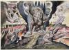
In 1938, Schonland put forward two possible explanations for the delay that causes the step-like nature of the leader. According to one of them, electrons should move down the channel of the leading streamer (pilot). However, some electrons are captured by atoms and positively charged ions, so that it takes some time for new advancing electrons to arrive before there is a potential gradient sufficient for the current to continue. According to another point of view, time is required for positively charged ions to accumulate under the head of the leader channel and, thus, create a sufficient potential gradient across it. In 1944, Bruce proposed a different explanation, which was based on the development of a glow discharge into an arc discharge. He considered a "corona discharge", similar to a tip discharge, existing around the leader channel, not only at the head of the channel, but along its entire length. He explained that the conditions for the existence of an arc discharge will be established for some time after the channel has developed over a certain distance and, therefore, steps have arisen. This phenomenon has not yet been fully studied and there is no specific theory yet. But physical processes, occurring near the leader's head are quite understandable. The field strength under the cloud is quite high - it is B/m; in the area of space directly in front of the leader's head it is even greater. The increase in field strength in this region is well explained by Fig. 4, where the dashed curves show sections of equipotential surfaces, and the solid curves show the field strength lines. In a strong electric field near the leader head, intense ionization of atoms and air molecules occurs. It occurs due to, firstly, the bombardment of atoms and molecules by fast electrons emitted from the leader (the so-called impact ionization), and, secondly, the absorption of photons of ultraviolet radiation emitted by the leader by atoms and molecules (photoionization). Due to the intense ionization of atoms and air molecules encountered on the path of the leader, the plasma channel grows, the leader moves towards the surface of the earth.
Taking into account stops along the way, it took the leader 10...20 ms to reach the ground at a distance of 1 km between the cloud and earth's surface. Now the cloud is connected to the ground by a plasma channel that perfectly conducts current. The channel of ionized gas seemed to short-circuit the cloud with the earth. This completes the first stage of development of the initial impulse.
The second stage proceeds quickly and powerfully. The main current flows along the path laid by the leader. The current pulse lasts approximately 0.1 ms. The current strength reaches values of the order of A. Stands out significant amount energy (up to J). The gas temperature in the channel reaches. It is at this moment that the unusually bright light that we observe during a lightning discharge is born, and thunder occurs, caused by the sudden expansion of the suddenly heated gas.
It is significant that both the glow and the heating of the plasma channel develop in the direction from the ground to the cloud, i.e. from bottom to top. To explain this phenomenon, let us conditionally divide the entire channel into several parts. As soon as the channel has formed (the head of the leader has reached the ground), first of all the electrons that were in its lowest part jump down; therefore, the lower part of the channel first begins to glow and warm up. Then electrons from the next (higher part of the channel) rush to the ground; the glow and heating of this part begin. And so gradually - from bottom to top - more and more electrons are included in the movement towards the ground; As a result, the glow and heating of the channel propagate in the direction from bottom to top.
After the main current pulse has passed, there is a pause lasting from 10 to 50 ms. During this time, the channel practically goes out, its temperature drops, and the degree of ionization of the channel decreases significantly.
However, the cloud still retains a large charge, so new leader rushes from the cloud to the ground, preparing the way for a new impulse of current. The leaders of the second and subsequent strikes are not stepped, but arrow-shaped. Arrowhead leaders are similar to the steps of a stepped leader. However, since the ionized channel already exists, the need for a pilot and stages is eliminated. Since the ionization in the channel of the swept leader is “older” than that of the stepped leader, recombination and diffusion of charge carriers occurs more intensely, and therefore the degree of ionization in the channel of the swept leader is lower. As a result, the speed of the swept leader is less than the speed of the individual stages of the stepped leader, but greater than the speed of the pilot. The speed values of the swept leader range from to m/s.
If more time than usual elapses between subsequent lightning strikes, the degree of ionization may be so low, especially in the lower part of the channel, that a new pilot becomes necessary to re-ionize the air. This explains individual cases of the formation of steps at the lower ends of the leaders, preceding not the first, but subsequent main lightning strikes.
As stated above, the new leader follows the path that was blazed by the original leader. It runs all the way from top to bottom without stopping (1ms). And again a powerful pulse of the main current follows. After another pause, everything repeats. As a result, several powerful impulses are emitted, which we naturally perceive as a single lightning discharge, as a single bright flash.
Basic conditions for logging into the system
Consumption (Nm3/h) 140.544
Consumption (kg/h) 192,000
H2O in gas (% volume) 2.3
CO2 in gas (% volume) 12.4
O2 in gas (% volume) 3.7
Temperature (°C) 270
Hours of operation (hours per year) 8,760
Design working pressure Positive
Dust load at system inlet PM (mg/Nm3) 512
Guaranteed output dust level PM (mg/Nm3) 10
PM system dust removal efficiency (%) 98.05
Other
Source of pollution cat cracking
Expected energy consumption (kW) 136
Full load consumption (kW) 279
Total pressure loss (mm in st)
Scope of delivery
Electrostatic precipitator (electrostatic precipitator):
We offer you one modular electrostatic precipitator, Model 39R-1330-3712P, which includes all plates, discharge electrodes, roof sections, insulation compartments, access doors, all internal components and power supplies to create a complete air pollution control module.
The electrostatic precipitator will have the following design features:
Pressure drop (mm in st) 12.7
Design temperature of the structure (gr C) 371
Design pressure of the structure (mm in st) +/- 890
Hopper volume (m3) 152
Number of bunkers 3
Neck dimensions 457 x 864
Number of gas passages 39
Transformer output voltage (kV) 55
Transformer output current (mA) 1100
Number of transformers 3
New, heavier design style settling plates made from solid steel sheets with a minimum thickness of 18mm. The sheets have a more rigid rigidity relief in the form of a box reinforced with stiffening ribs, which form a smooth flow of gas on the surface of the plate to minimize its re-entrapment. Both upper and lower guides, stiffeners and fasteners will ensure the alignment of the plates, compensating thermal expansion. The plates will be designed for maximum temperature up to 371 ° C
The design provides electromagnetic lifts and shakers with gravitational influence. Shaking systems will be designed to operate automatically and will be designed to minimize particle recirculation. The operating parameters of the shaker will have adjustable frequency and intensity characteristics.
The design includes rigid electrodes, which will be made of a seamless tube with a wall thickness of 1.7 mm with evenly distributed corona pins welded to the tube. The electrodes are level stabilized for operation in all temperature ranges of the precipitator.
Each discharge electrode frame will vibrate individually, and the system will be designed so that both the duration and frequency of vibration can be varied.
The precipitator is equipped with step transformers/rectifiers. Each kit is installed externally, equipped with oil insulation, and the rectifier is air cooled. The transformer and rectifiers are located in a single tank.
The transformer will be equipped with a grounding switch and a key lock. Each kit will be rated for a temperature of max + 45 degrees C (at maximum temperature environment+50 degrees C).
High voltage insulators are cylindrical, under compressive load.
The insulators are porcelain, glazed inside and out and have grounding terminals. The insulators are located outside the gas processing area and are cleaned with purge air.
The precipitator is equipped with key sequential safety locks to prevent access to any high voltage equipment without locking out the power supply and grounding the high voltage equipment. The following equipment will be locked: all precipitator quick access doors, transformer/rectifier and high voltage circuit breakers.
The scope of supply includes welded weather-resistant individual insulation compartments for insulators. Isolation compartments will be accessible by doors with safety interlocks to prevent access to all high voltage areas unless the precipitator is de-energized and grounded.
The electrostatic precipitator body will be made of 4.8 mm thick ASTM A-36 steel with external ASTM A-36 structural stiffeners that strengthen the structure to withstand internal pressure, wind, and other loads. The body is sealed by welding to form a completely gas-tight structure.
The precipitator is equipped with bins with a transverse tray. Each hopper is constructed from 3.8mm thick ASTM A-36 steel, which is reinforced with ASTM A-36 ribs. Each hopper is designed to support its weight when filled with particles. The particle density is 1041 kg/m3 for structural screening and 320 kg/m3 for hopper size. In addition, the bins will have sufficient capacity to store particles collected during a minimum period of 12 hours of operation. The side will be sloped to provide a minimum hopper wall angle of 60 degrees from horizontal. The end angle will be adjusted to provide a minimum hopper angle of 55 degrees.
Precipitator Supports: The precipitator will include all steel structures with self-lubricating sliding plates between the precipitator and the support structure. The structure will be designed to provide a clearance of 2438mm - 0mm between the hopper discharge and the ground.
Connections: The precipitator is equipped with flanged inlet and outlet connections. The pipes are made of ASTM A-36 steel with external stiffeners.
Inlet pipe: the inlet pipe is a horizontal pyramid type inlet with the lower angle of the pipe being 45 degrees from the horizontal. The inlet nozzle includes three distribution devices to ensure uniform flow through the precipitator. Organization of external access to the pipe is not required.
Outlet: The outlet is a horizontal pyramid type with the lower angle of the outlet 60° from the horizontal. The outlet pipe includes a flow distribution device to ensure uniform flow through the electrostatic precipitator. No access required.
Thermal Insulation and External Covering: The manufacturer will provide factory thermal insulation for the electrostatic precipitator (including housing, hopper, inlet and outlet pipes). Insulation will consist of 76mm thick 128kg/m3 density mineral wool on all surfaces except the electrostatic precipitator roof. The precipitator roof will be insulated with 152mm of 128kg/m3 density mineral wool plus 51mm fiberglass insulation over the stiffeners and then covered with a 6.4mm thick 'checkered plate' casing.
The insulation on the inlet, outlet and sides of the electrostatic precipitator will be covered with unpainted 0.8mm thick aluminum sheet type 3003, 1 x 4 box ribbed aluminum sheet or painted corrugated steel. The sheets will be installed vertically and will cover all seams in one section. The thermal insulation of the bins will be covered with unpainted 0.8mm thick aluminum sheet type 3003, 1 x 4 box ribbed aluminum sheet or painted corrugated steel. All roof joints will also be covered with flat materials.
The cover material will be secured using TEK No. 4.5 12-24 x 1¼" Weather Mounting Screws with Neoprene Washers. All sheet to sheet joints will be made using ¼ - 14 x 7/8" Pins with Neoprene Washers. All roof seams will be sealed with clear silicone sealant.
Painting: The manufacturer will paint structural supports, access hatches, insulation compartments, handrails and outer surface roof with one coat of red primer and one coat of industrial enamel paint. All hot metal surfaces that will be exposed after thermal insulation is completed will be painted with high temperature black paint. All stairs, platforms (including supports) and railings will be painted yellow for safety.
ELECTRICAL CONTROL: Following electrical equipment management will be provided in the project.
Protection class of equipment on the roof: Protection class 4 is established in accordance with EEMAC for the equipment on the roof of the precipitator, namely the control panel of the deposition plate shaker and the control panel of the electrode vibrator.
Blower Control Panel: The EEMAC Class 4 roof mounted blower control panel will be equipped with a built-in starter and start/stop controls.
T/R Controller: Each high voltage transformer/rectifier will be equipped with a microprocessor control panel in an EEMAC class 12 panel and the panel shall be installed in the customer's control room. All components of the panel will be accessible for maintenance through the hinged front door. Voltage control will be fully automatic with additional manual control. Both manual and automatic systems will provide complete control. Arc suppression will be provided by a current limiting device to reduce the voltage when a spark condition exists in the precipitator. The controllers are rated for a maximum ambient temperature of 40°C. All panel housings are made of 2.8mm steel and painted with ASA 61 gray enamel. We will provide you with a remote Graphics Voltage Controller (GVC) for each transformer/rectifier. Each GVC controller will be mounted on the front panel of a free-standing high voltage control box. The graphical controller provides bar graph and digital readouts of primary and secondary voltages and currents, as well as kW power, spark generation, SCR (Silicon Controlled Rectifier) conduction angle and T/R status. This controller must be installed in a safe area of the customer's control room. Alarms will be provided on the GVC control unit for overcurrent AC, T/R overheat, SCR high temperature, SCR imbalance, memory loss, DC undervoltage and DC overvoltage. A main menu is provided for selecting operating functions and troubleshooting. The graphics controller display is 16 lines of 40 characters. The device can produce voltage/current curves, 24-hour trend graphs and 30-minute trend graphs. The operator can remotely set all precipitator parameters such as rollback, lift speed, current limit, etc. Text is available in the help line to make all settings. Each controller will also have three indicators next to each GVC. These indicators are designed to indicate control on, HV on and alarm.
Current limiting reactor: For each transformer/rectifier there will be a current limiting reactor, protection class 3R according to EEMAC, which will be placed near the transformer/rectifier.
Factory-installed electrical equipment: We will install transformers/rectifiers at the manufacturer's factory and install high-voltage bus ducts and bus trays. We will provide conduit and cable management from the rooftop control panel/distribution panel (PCDP) for shakers, vibrators and blowers. We will install all high-voltage insulators, vibration isolators and power supply insulators. We will supply and install terminal boxes for all roof connections (customer's responsibility for initial connection conditions).
Wired harness
We use following types wiring for the connections below (we reserve the right to replace the XLPE wire below):
Cable cable channels
This cable is used between panels and junction boxes on the roof, and between these junction boxes and the terminals of shakers, blowers and vibrators. Channels will have a nominal 40% capacity in accordance with N.E.C.
THHN/MTW/THWN-2/T90 copper conductor
Underwriters Laboratories Standards UL-83, UL-1063, UL-758
AWM Specification 1316, 1317, 1318, 1319, 1320, 1321
ASTM twist class B3, B8, B787
Federal Specification A-A-59544
Canadian Association Standard C22.2 No. 75
NEMA WC70/ICEA S-95-658
Institute of Electrical and Electronics Engineers ARRA 2009; Section 1605
Conductor: Stranded bare copper conductors per ASTM-B3, ASTM-B787 and ASTM-B8
Insulation: Colored polyvinyl chloride (PVC), heat and moisture resistant, fire retardant compound to UL-1063 and UL-83
Sheath: Rigid polyamide, nylon to UL-1063 and UL-83. Slippery, nylon outer shell for easy draw. VW-1 is rated 14 AWG - 8 AWG. All sizes are petrol and oil resistant.
Applications: Typical THHN/THWN-2 construction wire is intended for general purpose applications as defined by the National Electrical Code (NEC). Type THHN/THWN-2 is approved for new construction or reinstallation for 600 volt applications. Applications requiring Type THHN or THWN-2: The conductor is suitable for use in wet or dry locations at temperatures not exceeding 90°C or not exceeding 75°C in oil or refrigerants. Applications requiring MTW type: The conductor is suitable for use in dry locations at 90°C or should not exceed 60°C in wet locations or when exposed to oils or coolants. Applications requiring Type AWM: The conductor is suitable for use at temperatures not exceeding 105°C in dry locations.
Vibration isolation wire
This wire is used between duct junction boxes and shakers, blowers and vibrators.
SOOW/SJOOW 90ºC Black ROHS
Engineering Specification/Standards:
UL Standard 62
NEC Article 501.140 Class I Div. 2
NEC Article 400
CSA C22.2 No. 49
CSA FT2 flame test
EPA 40 CFR Part 26 Subpart C Heavy Metals Table 1 TCLP Method
Conductor: 18 AWG - 10 AWG Class K stranded bare copper per ASTM B-174
Insulation: EPDM
Shell: CPE
Legend: SOOW E54864 (UL) 600V -40C TO 90C -- CSA LL39753 SOOW 600V -40C TO 90C FT2 Waterproof P-07-KA070018-1-MSHA
Applications: Manufactured using advanced synthetic rubber compounds to perform in temperatures ranging from -40°C to 90°C with excellent resistance to flame, deformation, ozone, oils, acids and chemicals. SOOW has wear-resistant and oil-resistant insulation and casing. SOOW is flexible in low temperatures and exceptionally flexible in normal conditions for electric motors, portable lamps, battery chargers, portable lighting fixtures and portable equipment. National Electrical Code Section 400 Appendix.
Wire for connecting panels
This wire is used to connect various components inside panels (switches, lights, plc, blocks, fuses, terminals, etc.).
MIL-W-16878/2 Type C wire (M16878/2 wire) / Mil-DTL-16878/2
Engineering Specification/Standards:
UL VW-1 flame test
RoHS Hook-up Wire RoHS compliance
MIL-W-16878/2 Type C wire (M16878/2 wire)
Description:
Conductor: Tinned copper, solid and stranded
Insulation: Polyvinyl chloride (PVC), colored
Application: The connecting wire complies with UL VW-1 flame test and is used in a wide range of industries requiring high temperature wire that can also withstand harsh conditions. Due to its size, non-flammable materials and resistance to chemicals Typical applications for MIL-Spec wire include complex applications for the military or aerospace industry. The wire can also be used for internal wiring of electronic equipment. The wire has a temperature range of -55°C to +105°C (M16878/2 Type C) and 1000 volts. All MIL Spec cable types have excellent temperature range and voltage ratings. M16878E connects to wired applications: military equipment, power wire, electrical appliance wiring and medical electronics. M16878EE can be used for electronic use in rugged applications where high temperatures are encountered and is a highly reliable OEM product. The M16878ET is used in aerospace, industrial, military and many other commercial markets.
Targets and guarantees
DEFINITION: The equipment we offer here under design conditions and an input dust load of 512 mg/Nm3 guarantees a dust content at the outlet of the precipitator of no more than 10 mg/Nm3, which is 98.05% of the input load. If the input specific load exceeds the design one, the efficiency of 98.05% is also guaranteed; if the specific load is equal to or less than the calculated one, a residual dust content of 10 mg/nm3 is guaranteed.
OPACITY: The plant guarantees an average flue gas opacity of less than 10% for one hour when operating at design conditions. Transparency must be determined by a certified smoke reading device or certified opacity monitor.
Particle Testing Qualification: The particulate sampling method will be EPA Method No. 5 as specified in the Federal Register. Particles are defined as solids under the operating conditions of the precipitator that can be collected. Condensates are not included here.
An electric spark has the appearance of a thin, whimsically curved and brightly luminous strip, which is usually highly branched (Fig. 174). This luminous channel of the spark, however, is never at all similar to those acute-angled zigzags with which it is customary to conventionally depict lightning.
Rice. 174. Characteristic appearance sparks.
A strip of spark with enormous speed penetrates the discharge gap, goes out and appears again. Photographing a spark using a camera with a fast-moving lens (Base camera) or with fast-moving film shows that several discharges run along the same channel of the spark, which is sometimes deformed. To study individual stages of spark development, photogates controlled by high-frequency current and based on the use of the Kerr phenomenon are used (§ 95). One of the first studies of the structure of the spark was carried out by Prof. Rozhansky in 1911 Rozhansky photographed a spark, deflecting the spark by the action of a magnetic field.
Gas breakdown, resulting in a spark discharge, occurs at a certain field strength, which should be greater, the higher the density of the gas and the lower its initial ionization.
Below are numerical data characterizing the size of the spark gap in room air. The electric field strength near the electrodes strongly depends on the curvature
surface of the electrode, therefore the minimum voltages at which for given distance an avalanche discharge begins between the electrodes; they are not the same for the electrodes various shapes; between the tips, the spark discharge begins at a lower voltage than between the balls or plr electrodes.
The spark gap in room air
(see scan)
Room air usually contains only a very small number of ions, approximately a few thousand per cubic centimeter(under normal electrical state of the atmosphere at the surface of the earth - on average about 700 pairs of ions per 1 cm

Rice. 175. Scheme of development of a negative streamer
When a sufficiently high voltage is applied to the electrodes, electron avalanches begin to grow, but due to the small initial number of ions, it takes time for the process to end with the formation of a spark. If you connect the electrodes to a high-voltage current source for an extremely short time, then the development of electronic labs will not have time to end with a spark discharge. Measuring the time during which channels of increased electrical conductivity are formed in the gas due to the development of avalanches showed that in in this case Photon ionization plays an important role.
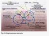
In Fig. 175 presents a diagram explaining why the growth of an electrically conductive channel, or, as they say, the spread
streamer, occurs faster than the advancement of an electronic avalanche. In this figure, avalanches are conventionally shown as shaded cones, and the paths of photons are depicted as wavy lines. One must imagine that inside each cone representing a developing avalanche, the gas is ionized by electron impacts; newly detached electrons, accelerated by the field, ionize the gas particles they encounter, and thus the number of electrons moving to the anode and the number of positive ions drifting to the cathode increase exponentially. The left ends of the wavy lines show atoms that were “excited” by an electron impact and subsequently emitted a photon. Moving at speed, photons overtake the avalanche and in some place, which is depicted by the end of the wavy line, ionize a gas particle. The electron split off here, rushing towards the anode, generates a new avalanche far ahead of the first avalanche. Thus, while the first avalanche grows, say, by the amount of the small arrow shown in Fig. 175, the emerging channel of increased electrical conductivity of the gas, i.e., a streamer, extends to the size of the large arrow shown in the same figure. In the next stage, individual avalanches in the negative streamer, overtaking each other, merge, forming an integral channel of ionized gas (in the figure, the first avalanche has already overtaken the second, and the fourth has overtaken the fifth).
The physical and mathematical conditions under which streamer development can occur were theoretically studied by Meek and Loeb in 1940). As already explained above, a negative streamer is, in essence, the advancement of electron avalanches accelerated by photoionization and their merging into a common electrically conducting channel.
The positive streamer has a completely different structure and significantly different properties. A common feature Its only relationship with a negative streamer is photoionization, which in both cases plays a dominant role.
A positive streamer is a gas-discharge plasma channel that rapidly grows from the anode to the cathode. In Fig. 176 schematically explains how such a channel develops. The appearance of a positive streamer is preceded by the passage of electron avalanches across the gas-discharge gap. They leave in their wake large number newly formed positive ions, the concentration of which is especially high where avalanches are most developed, that is, near the anode (Fig. 176, top left). If the concentration of positive ions here reaches a certain value (close to ions in ), then, firstly, intense photoionization is detected, secondly, electrons released by gas particles that have absorbed photons are attracted by a positive space charge to the head part of the positive streamer, and, thirdly, due to photoionization, the concentration of positive ions on the path of the streamer to the cathode increases. In Fig. 176 photon paths are shown as wavy lines; photons are ejected in different directions from the region of positive space charge (short arrows indicate the direction of movement of the split-off electrons); It can be seen that many electrons are drawn into the region of the highest concentration of positive ions in the head part of the positive streamer. The saturation of space filled with positive charges with electrons turns this area into a gas-discharge plasma.

(click to view scan)
This creates a channel in the gas that has high electrical conductivity. The formation of this channel with gas-discharge plasma is the development of a positive streamer (Fig. 176). If along the path of growth of this channel towards the cathode in the head part of the streamer there is a sufficient concentration of positive ions, then the streamer moves at enormous speed. Otherwise it breaks off.
The streamer development diagrams explained above give only an approximate idea of the preparatory stage of the spark discharge. The actual picture of streamer development is more complex, since the resulting space charges sharply distort the electric field that caused the streamer to appear.
In long gas-discharge gaps, field unevenness and insufficient photoionization in the direction shortest distance from the head of the streamer to the electrode lead to curvature of the channel and the appearance of numerous branches.
The development of positive streamers begins at the positive electrode in places of the highest field strength: near sharp protrusions, sharp edges and other irregularities in the anode surface. Therefore, during a discharge between the tip and the disk, sparks are often observed connecting the positive tip with the center of the negative disk, and sparks connecting the edges of the positively charged disk with the negative tip (Fig. 177); in the first case, breakdown occurs at a lower voltage.

Rice. 177. Characteristic appearance of a spark discharge between the tip and the disk with a large discharge gap.
Rice. 178. Photograph of a spark on moving film.
Field deformations by charges formed in the streamer and a combination of complex processes occurring in the streamer lead to the fact that the spark discharge often develops in jerks. At the same time
a new streamer retraces the path paved by the previous faded streamer. In Fig. 178 shows a photograph of a single spark discharge on. fast moving photographic film. Here you can see the jerky development of the spark and it is clear that the negative and positive streamers are growing towards each other. When the heads of the streamers meet, a conductive channel is formed, through which the discharge occurs.
A similar, but even more complex picture is revealed during the development of lightning. The initial stage is the development of a pilot lightning streamer, the glow of which is almost imperceptible. Typically, the pilot streamer propagates from a negatively charged cloud. Along the still narrow channel of increased ionization formed by the piloting lightning streamer, powerful electron avalanches rush at a speed of about thousands of kilometers per second, creating a rather bright glow. In this case, the electrical conductivity of the channel increases enormously and the cross section of the channel expands. This stage is called lightning leader development. When the initial ionization of the air is low, the development of the leader occurs spasmodically - with stops of tens of milliseconds after each of its propagations (such leaders are called “stepped” in contrast to the so-called “lancet”, which propagate with continuous rapidity).

Rice. 179. Photograph of lightning on moving film. Here the pauses between the first beats and the last pause are four times longer.
As the leader approaches the ground, charges are induced in the ground opposite sign, and an oncoming leader grows from tall buildings, lightning rods, and trees. At the moment of its merger with the leader descending from the cloud, i.e., when the discharge gap between the cloud and the ground turns out to be a closed electrically conductive channel, the main lightning discharge runs through this channel at a speed of the order of tens of thousands of kilometers per second. If the channel had branches (and this usually happens), then the main discharge spreads across all branches Diameter of the main channel
Lightning usually has a size of 10-20 cm and the brightest glow is in the lower part. Created in the channel high blood pressure, which after a lightning strike causes a rupture of the channel, which gives rise to the phenomenon of thunder. The charge carried by lightning is usually several coulombs and often several tens of coulombs. The instantaneous value of the lightning current is often tens and sometimes hundreds of thousands of amperes.
A lightning discharge usually carries away charges only from some part of the cloud. Charges from other parts of the cloud rush to this place. Therefore, most often, after the first lightning strike, after hundredths of a second, repeated lightning strikes (two, three or more) occur along the same, but sometimes somewhat deformed or otherwise branched channel; each of them is preceded by a leader that restores the electrical conductivity of the channel.

Rice. 180. Diagram of a thunderstorm (cumulonimbus) cloud.
Rice. 179 reproduces a picture of five lightning strikes on one channel, filmed on moving film. In some cases strong wind It shifts the lightning channel in such a way that even when photographing with a conventional camera, individual strokes can be distinguished.
In Fig. 180 shows a diagram of the most common charge distribution in a thundercloud. Negative charges are usually distributed at the leading edge of the cloud and along its lower part. There is also a region of positive charges here; everything is also positively charged upper part clouds. The direction of the wind (indicated by arrows in the figure) blowing the cloud away is usually opposite to the ground wind. At first, heavy rain takes away the positive charge from the cloud, later moderate, negatively charged rain falls.
In the absence of a thunderstorm, the electric field in the atmosphere is directed from top to bottom, since the earth is negatively charged, and the positive charge is scattered in the atmosphere.
When there are no disturbing influences created, in particular, by thunderclouds, the electric field strength in the atmosphere decreases with height. Near the earth, the electric field strength is of the order of magnitude. At an altitude it is equal to, and at an altitude approximately The field strength at an altitude of 20 km is 100 times less than that of the earth.
This rapid decrease in electric field strength with height shows that, compared to uniform field The electric field in the atmosphere is very complicated by the charges distributed in the atmospheric air.
During thunderstorms, the field strength in the atmosphere can be 100 and 1000 times higher than normal.
Under a thundercloud, the field direction most often reverses, from the ground to the negatively charged lower edge of the cloud, and the field strength near the ground before a lightning discharge can reach 200-300 thousand volts per meter. The potential difference between cloud and ground before a lightning strike is often hundreds of millions and sometimes billions of volts. Most lightning strikes come from negatively charged clouds. Lightning bolts are often several kilometers long. Lightning strikes often occur between individual clouds. Thunderstorms were observed, during which there were 4-7 thousand lightning strikes per hour. On average, about 44 thousand thunderstorms occur on the globe per day (an average of about 1800 thunderstorms at a time) and several thousand lightning strikes occur every minute.

Rice. 181. Photograph of ball lightning
In rare cases, lightning discharges of a completely different type are observed. In Fig. 181 one of the photographs of ball lightning is reproduced. According to observers' descriptions, ball lightning usually looks like glowing balls with a diameter of about 10-20 cm, and sometimes several meters. Ball lightning moves smoothly, at low speed and in some cases abruptly. There have been cases when ball lightning, touching the ground or any objects, exploded and caused severe destruction.
Numerous attempts to reproduce this type of discharge in the laboratory did not give satisfactory results, despite the fact that some researchers (Plante in Gezehusu in 1900, Cawood et al.)
It was possible to obtain spherical type discharges. In Fig. 182 Plante's experience is explained. If, using a high voltage source DC voltage, immerse the anode in the electrolyte and bring the cathode to the surface of the electrolyte, then an arc discharge is ignited. But when the cathode is immersed in the electrolyte and the anode is brought to the surface of the electrolyte, an arc cannot form, since the possibility of incandescence and thermionic emission from the dathode is excluded. Plante discovered that in this case, under certain conditions, a luminous and rapidly rotating ball is formed between the anode and the surface of the electrolyte, which after some time slides along the surface of the electrolyte to the cathode.

Rice. 182. Scheme of Plante's experiment.

Rice. 183. Photo of beaded lightning.
One of the many hypotheses proposed to explain ball lightning (Meissner's hypothesis) interprets this type of discharge as a vortex of gas-discharge plasma occurring in the bend of linear lightning. According to another hypothesis (Mathias), it is assumed that in ball lightning the energy of the discharge is chemically accumulated, and unstable higher compounds of nitrogen and oxygen are formed, capable of decomposing with an explosion.
Sometimes lightning turns out to consist of several dozen small luminous balls (less than 10 cm in diameter), separated from each other by a distance of less than a meter. This type of discharge is called imprecise lightning (Fig. 183). There is not yet an acceptable, sufficiently substantiated theory of ball and bead lightning.
If, when using a high direct voltage, a plate made of a solid dielectric (glass, ebonite, etc.) is placed between the electrodes and this plate has such a thickness that a spark does not penetrate it, and the width is not too large, then a sliding spark discharge is observed, which passes along the surface of the plate and bends around it. To study this discharge, it is created on a photographic plate and then developed (Fig. 184). The discharge images obtained in this way are called Lichtenberg figures. Their radius is proportional to the voltage of the discharge pulse. This is used (using special devices for photographing a sliding discharge - klidonographs) in a massive, statistical study of lightning"
In the USSR, a systematic study of lightning and lightning protection methods is being conducted. The leading role in this area belongs to the high-voltage laboratory of the Energy Institute of the USSR Academy of Sciences.
When the voltage is not high enough to break down the gas-discharge gap, special type discharge-corona.

Rice. 184. The sliding will discharge the positive electrode.
Corona discharge on high-voltage networks causes power leaks.
A study of the corona showed that on the positive electrode the corona discharge at relatively low voltages consists of a series of electron avalanche pulses, lasting every ten-thousandths of a second. At higher voltages, the intermittency of the phenomena is less noticeable and the main role is played by streamers, breaking off where the field strength is too low for their propagation. The structure and character of the glow of the corona discharge on the negative electrode are to some extent similar to the near-cathode zone of the glow discharge.
Spark discharge.
If an electric field of about 3·10 V/m appears between two electrodes in the air, then electric spark in the form of a brightly glowing, complexly curved thin channel connecting both electrodes (Fig. 4.8).

An example of a spark discharge is lightning. The features of such a discharge are explained by the theory of streamers. According to this theory, the appearance of a brightly glowing spark channel is preceded by the appearance of individual weakly glowing clusters of ionized particles. In the gap between the electrodes, these streamer clusters form conducting bridges, along which a powerful flow of electrons then rushes. The reason for the appearance of streamers is both the formation of electron avalanches and photoionization, i.e. ionization of gas by radiation arising in the discharge. As a result, secondary avalanches are formed, which catch up with each other, forming a well-conducting channel. Thus, the current strength in the lightning channel can be from 10 to 10 A, and the voltage between the cloud and the ground before the occurrence of lightning reaches 10 - 10 V.
Filming with a camera with a rotating lens showed that lightning is preceded by the development of a weakly luminous channel - the leader, spreading from the cloud to the ground at a speed of 10 - 10 m/s. In this case, strong heating of the air occurs in the main channel and shock occurs. sound wave– thunder.
In industry, electric spark processing of metals is used - surface hardening and drilling.
Corona discharge.
If one electrode is thin (wire) and the other has a large surface (cylinder) (Fig. 4.9), then a non-uniform electric field occurs. The field lines near the wire become denser and, at a field strength of 3·10 V/m, electron avalanches and a glow in the form of a crown appear near the wire.

As you move away from the wire, the field strength decreases and the electron avalanches break off.
Corona discharge occurs at a negative potential on the wire, at a positive voltage, and at an alternating voltage between the wire and the cylinder. Only the direction of the avalanches changes.
Electrons flying out of the corona attach to neutral atoms, charging them negatively. This is used in electrostatic filters for purifying industrial gases. Gas and dust are passed through a wire-cylinder system of electrodes. The dust is charged by adhering electrons and attracted to the cylinder, then shaken off into the hopper, and dust-free gas is released into the atmosphere.
Corona discharge can occur near any thin conductors or points. Such a discharge was observed in the pre-storm period on the tops of ship masts and trees. You can observe the ignition of the corona near wires under high voltage. To prevent corona discharge and leakage currents, the conductors must have a sufficiently large diameter.
Arc discharge.
The arc discharge was discovered in 1802 by professor of physics V. Petrov. He received a discharge in the form of a luminous arc, pushing apart two carbon electrodes, previously brought into contact and connected to a powerful battery of galvanic cells. At the point of contact, the circuit resistance is high and strong heating occurs, the coals become hot. As a result, thermionic emission occurs from the cathode. Electrons bombard the anode, forming a depression in it - a crater. The anode temperature is about 4000 K, at 20 atm it can rise to 7000 K. The current strength reaches tens and hundreds of amperes, and the voltage across the discharge gap is several tens of volts. This type of arc is used for welding and cutting metals.
4. Plasma is a highly ionized gas in which the concentrations of positive ions and negative electrons are almost equal. Plasma can be high-temperature, obtained at high temperatures by thermal ionization of atoms, for example, with thermonuclear fusion or in the area of an arc discharge. Gas-discharge low-temperature plasma occurs in an electric field.
Plasma is similar to ordinary gases and obeys gas laws. However, in electrical conductivity it approaches metals; it is characterized strong interaction with electric and magnetic fields. The presence of mobile differently charged particles is accompanied by their recombination and glow.
Plasma is used in magnetohydrodynamic (MHD) electric current generators. Low-temperature plasma is used in gas lasers and plasma TVs.

LECTURE 5
Subject: Magnetic field in vacuum and in matter
Questions: 1) The effect of a magnetic field on a current-carrying conductor. Magnetic
induction.
2) Magnetic field of a conductor carrying current. Biot-Savart-Laplace law.
3) Circuit with current in a magnetic field.
4) Work in a magnetic field.
1. In 1820, Ampere discovered the effect of current on a magnetic needle: when current is passed through a conductor, the magnetic needle located next to it turns perpendicular to the conductor. Ampere's experiments showed that current-carrying conductors are attracted to each other if the currents flow in them in one direction, and repel if the currents flow in opposite directions. Thus, it was established that there is a magnetic field around current-carrying conductors. It can be detected by its action on a current-carrying conductor or permanent magnet.
Let a straight conductor of length l with current I(Fig. 5.1).

From experiments it was established that a force (Ampere force) acts on a conductor from the magnetic field.
F= I l B sin α,
where α is the angle between the conductor and the direction of the magnetic field.
The direction of the force can be determined by the rule of the left hand (if four fingers are positioned in the direction of the current, and the magnetic field lines enter the palm, then the bent thumb will show the direction of the force).
If the angle α between the directions of the vector IN and the current in the conductor is different from 90°, then to determine the direction of the force it is more convenient to use the gimlet rule: an imaginary gimlet is located perpendicular to the plane containing the vector IN and a conductor with current, then its handle turns from the direction of the current to the direction of the vector IN. The forward movement of the gimlet will indicate the direction of the force. The gimlet rule is often called the right screw rule.

The ampere strength depends on both the current strength and the magnetic field. Magnitude IN called magnetic induction and serves as the main force characteristic of the magnetic field.
If we put I = 1 A, l= 1 m, α = 90º, then B = F. This implies physical meaning B. Magnetic induction B is a physical quantity numerically equal to the force with which a magnetic field acts on a straight conductor of unit length with a current of unit strength, located perpendicular to the magnetic field lines.
Unit of measurement of magnetic induction: [B] = N/A m = T (tesla).
Now it becomes clear why two current-carrying conductors attract or repel: depending on the direction of the currents, the magnetic field of one conductor pushes out or retracts the other current-carrying conductor.

It is convenient to represent a magnetic field using lines of force. An idea of such lines is given by the location iron filings near the poles permanent magnet.

A magnetic induction line (field line) is a line drawn in a magnetic field, the tangent to which at any point coincides with the magnetic induction vector at that point. The magnetic induction lines are closed and surround the current-carrying conductor. The fact that the lines of force have no beginning indicates the absence of magnetic charges.

The direction of the power lines is determined by the gimlet rule: if you screw in the gimlet so that the screw moves in the direction of the current, then the direction of movement of the handle will coincide with the direction power line. The density of the field lines is proportional to the magnitude of the magnetic induction. Near a conductor with current, the magnetic field is non-uniform; the closer to the conductor, the stronger the field and the denser the lines of force. A uniform magnetic field can be created inside a long coil carrying current.
As can be seen from Figure 5.6, the magnetic field of a current-carrying coil is similar to the magnetic field of a permanent magnet, i.e. has a “northern” end N, from which the ley lines exit, and a “south” S, into which the ley lines enter. Indicative magnetic needles are oriented in the direction of the tangents to the induction lines.

Let us introduce the concept of magnetic flux or flux Ф of the magnetic induction vector through the area S: Ф =В Scosα, where α is the angle between the normal (perpendicular) to the area and the magnetic induction IN.
The unit of measurement for the flux of the magnetic induction vector [F] = T m² = Wb (Weber).

If the field is nonuniform and the surface is not flat, then it is divided into infinitesimal elements dS so that each element can be considered flat and the field uniform. The flux of the magnetic induction vector through the surface element dФ = ВdScosα, and through the entire surface

2. As a result of many experiments by different scientists, the Biot-Savart-Laplace law was derived, which allows one to calculate the magnetic induction of fields created by current-carrying conductors.
Then the magnitude of magnetic induction at a point distant from the conductor at a distance r is determined according to the Biot-Savart-Laplace law, as
 ,
,
where the value μ0 = 4π·10 H/m is called the magnetic constant.
Direction of vector d IN perpendicular to the plane in which d lie l and r. Vector d IN directed along a tangent xyl line drawn through the field point in question, in accordance with the gimlet rule.
For a magnetic field, the superposition principle applies: if there are several current-carrying conductors, then the magnetic induction at any point is equal to the vector sum of the magnetic inductions created at this point by each conductor separately. The principle of superposition is also valid for current elements. By applying the Biot-Savart-Laplace law and the principle of superposition together, it is possible to determine the magnetic induction of various current-carrying conductors.

Example. Magnetic field in the center of a circular conductor carrying current.
The magnetic inductions of each current element dl in the center are directed in one direction, perpendicular to the plane of the conductor contour, and are simply summed up. This can be understood if we draw the field lines of each element of a current-carrying conductor through the center and construct tangents to them. The direction of the magnetic induction of a circular conductor carrying current can also be determined by the gimlet rule: if you screw in the gimlet by rotating the handle in the direction of the current, the screw will show the direction of the magnetic induction in the center.
The magnitude of magnetic induction is determined by the Biot-Savart-Laplace law

Created circular currents It is convenient to describe magnetic fields using the magnetic moment pm = IS, where I is the current in the circuit, and S is the area flown around by the current. The direction of the magnetic moment is taken to be the direction of the normal to the plane of the coil, which coincides with the direction of the vector IN in the center. Then ![]()
It can be shown that the magnetic induction inside a long coil with current (solenoid) is B = μ0μnI, where n is the number of turns per unit length of the coil.
3. Place the conductor, bent in the form of a rectangular frame, in a uniform magnetic field.

When current flows through a conductor, a force from a magnetic field acts on each side of it. Tensile forces act on the upper and lower sides of the contour. The forces acting on the lateral sides are F1 = F2 = IB l sin90º, where l- side length. Each of these forces creates a torque M = Fd, where d is the force arm.
Moment of a couple of forces M = 2Fd.= 2IB l d. From Fig. 5.10 it is clear that. Then M = IB la sinα or M = IBSsinα, where S is the area of the frame. The current-carrying circuit rotates until its torque becomes equal to zero, i.e. angle α will become zero. Thus, a frame with current in a magnetic field tends to turn perpendicular to the lines of force. You can relate the torque and magnetic moment of the circuit to the current
The torque ceases to act when the magnetic moment of the current-carrying circuit is oriented along the direction of the magnetic induction of the field.
Fig.5.11
3. A magnetic field can move a current-carrying conductor, which means the field does work. Let a straight conductor of length l under the influence of a uniform magnetic field will move a distance dx in the direction perpendicular to the magnetic field lines.

Fig.5.12
Work dA = Fdx = I l Bdx. Since the product of displacement and the length of the conductor is the area dS described by the conductor during movement, then dA = IBdS, or dA = IdФ. Consequently, the work done to move a conductor in a magnetic field is equal to the product of the current in the conductor and the magnetic flux passing through the area described by the conductor during movement.
LECTURE 6
Subject: The effect of a magnetic field on a moving charge . Magnetic field in
substance
Questions: 1) Lorentz force.
2) Movement of a charge in a magnetic field.
3) Magnetic field in matter.
4) Ferromagnets.
1. A conductor carrying current creates a magnetic field in the surrounding space. Since electric current represents the directed movement of charged particles, any moving charge creates a magnetic field. You can write down the Biot-Savart-Laplace law for one charge. To do this, we transform Idl = jSdl = nqvSdl = Nqv. Here j is the current density, n is the number of charged particles per unit volume (particle concentration), v is the particle speed. N – full number particles in the segment dl of the conductor. Now the magnetic induction created by a piece of current-carrying conductor can be represented as
 ,
,
and the magnetic induction of the field created in a vacuum by one charge q at a distance r from the charge


The direction of the lines of force is determined by the gimlet rule.
The magnetic field acts on the current, which means that a force must also act on each charge. G. Lorentz received the expression for it.

A charge q moving in a magnetic field with a speed v is acted upon by a force F = qvBsinα, where α is the angle between the direction of speed and magnetic induction. Direction of force for positive charge determined by the rule of the left hand or the right screw (rotate from v To B).
Thus, there is both electrical and magnetic interaction between moving charges.
2. Let a particle with charge q and speed v fly into a uniform magnetic field perpendicular to the lines of magnetic induction B (Fig. 6.3).

The force acting on the particle is F = qvBsin90º. The force is perpendicular to the speed, which means it does no work and does not change the energy and speed of the particle. However, a force perpendicular to the velocity always causes centripetal acceleration and movement in a circle, i.e.
The greater the particle speed, the greater the radius of the trajectory circle. As magnetic induction increases, the radius decreases. It also depends on the specific charge q/m of the particle.
The period of revolution of the particle is T = 2πR/v. Substituting the expression for the radius, we get, i.e. the period does not depend on speed.
Let now a charged particle fly into a magnetic field at an angle α to the direction of magnetic induction (Fig. 6.4).

In this case, the particle speed v0 can be represented as the vector sum of the tangential velocity vt directed along B and the normal velocity vn perpendicular to B.
vt = v0 cosα, substituting this speed into the expression for the Lorentz force, we obtain F = qvtBsin0º, i.e. F = 0. This means that along the line of force the force does not act on the particle and it moves uniformly and rectilinearly in this direction.
vn = v0 sinα,. Lorentz force F = qvnBsin90º causes centripetal acceleration and circular motion with radius and period. As a result, the particle describes a trajectory in the form of a cylindrical spiral with a pitch (the distance between the turns of the spiral by which the particle moves along the line of force after making one full revolution) f = vt T.
The patterns of motion of charged particles in magnetic and electric fields are used in accelerators, magnetrons, mass spectrometers, etc.

3. All substances consist of atoms and molecules, the movement of electrons in which represents closed molecular currents. Each of these currents creates a magnetic field, i.e. has a magnetic moment
where I is the current strength, S is the area flown around by the current, n- unit vector normal to the plane of the coil with current.
Under normal conditions, as a result of the thermal motion of particles, the magnetic moments of molecular currents are misoriented. If you place a substance in a magnetic field, then the magnetic moments of the particles are partially or completely oriented along the external magnetic field, strengthening it (Fig. 6.6).

Substances that can be magnetized are called magnets. Magnetic state a substance is characterized by a magnetization vector, i.e. magnetic moment per unit volume of a substance

The unit of measurement for magnetization is tesla. For convenience of consideration, we introduced the physical quantity N – magnetic field strength. This power characteristic magnetic field, related to magnetic induction by the relation. It characterizes the magnetic field in a vacuum. From experiments it follows that the magnetization vector is proportional to the magnetic field strength ![]() , where χ is the magnetic susceptibility of the substance.
, where χ is the magnetic susceptibility of the substance.
Full meaning magnetic induction in a magnet is equal to
This means that magnetic induction in a substance ![]() , where μ is the magnetic permeability of the substance. It shows how many times the magnetic field in a substance is stronger than in a vacuum.
, where μ is the magnetic permeability of the substance. It shows how many times the magnetic field in a substance is stronger than in a vacuum.
There are some substances for which μ<1, их называют диамагнетиками (азот, вода, серебро, висмут). У них магнитный момент молекулярных токов устанавливается против поля, что объясняется появлением дополнительного вращения электронных орбиталей (прецессии) в магнитном поле.
Many substances have μ >1, they are called paramagnetic (oxygen, aluminum, etc.). For diamagnetic and paramagnetic materials, the magnetic permeability is close to unity, i.e. they are weakly magnetized.
At the interface between two different environments With different meanings magnetic permeability, magnetic induction lines are refracted. The normal component of the magnetic induction wind does not change
The induction components tangent to the interface experience a jump, and
From these formulas follows the law of refraction of induction lines
where is the angle between the magnetic induction lines in medium 1 and the normal to the interface, and is the corresponding angle in medium 2. This means that the induction lines, entering a medium with greater magnetic permeability, move away from the normal and become denser (Fig. 6.7).


Fig.6.7 a – ball in a magnetic field (μ of the ball is greater than μ of the medium);
b - ball in a magnetic field (μ of the ball is less than μ of the medium);
c - an iron cylinder is placed in an initially homogeneous
magnetic field
4. There are substances that are capable of being strongly magnetized; their magnetic permeability is on the order of thousands of units and can reach a million in special cases. Iron and its alloys exhibit such properties, which is why this class of substances is called ferromagnets. Other metals also exhibit ferromagnetic properties (Table 6.1).
Table 6.1 Ferromagnetic metals
Ferromagnets are substances (usually in solid crystalline or amorphous state), in which below a certain critical temperature TC (Curie point) a long-range ferromagnetic order of the magnetic moments of atoms is established. In other words, a ferromagnet is a substance that, when cooled below a certain temperature, acquires magnetic properties. Above the Curie point, ferromagnetic properties disappear.
Ferromagnetic materials are characterized by strong orientation of the magnetic moments of atoms without an external magnetic field. As a result of the exchange interaction of electrons, separate areas of spontaneous magnetization are formed - domains. Such domains were experimentally discovered using powder figures. A layer of liquid with iron oxide powder is placed on a well-polished surface of the ferromagnet. The grains settle in places where the magnetic field is inhomogeneous, that is, at the walls of the domains, and the boundaries of the domains are clearly visible in the microscope (Fig. 6.7).

Rice. 6.7 a – without magnetic field; b – magnetic field perpendicular to the drawing plane; c – magnetic field in the opposite direction.
The directions of magnetization in individual domains are different and are such that the total magnetic moment of the ferromagnet is zero. When an external magnetic field is turned on, domains grow in which the magnetization vector makes an acute angle with the direction of the external magnetic field, and the volume of the domains with obtuse angle decreases.

Fig. 6.8 The process of magnetization of a ferromagnet: a, b, c – displacement
boundaries; d and e – rotation of the magnetization vector
In the case of weak fields (region 1), the displacements of the boundaries are reversible and exactly follow the change in the field. As the field increases, the displacement of domain boundaries becomes irreversible and unfavorable domains disappear. Then, with an even greater increase in the field, the direction of the magnetic moment inside the domain changes. In a very strong magnetic field, the magnetic moments of all domains are set parallel to the field and the ferromagnet is now magnetized to saturation.
All these magnetization processes occur with some delay, that is, they lag behind the field change; this phenomenon is called hysteresis (Fig. 6.8).

Fig.6.9 Hysteresis loop
If you decrease the magnetic field, then when the field H becomes equal to zero, residual magnetization +B is observed in the magnet. To completely demagnetize a magnet, it is necessary to apply a magnetic field of the opposite sign –Hc. This field is called the coercive force of a ferromagnet.
When a ferromagnet is cyclically remagnetized, the change in induction in it will be represented by a hysteresis loop. The work during cyclic magnetization reversal is proportional to the area of the hysteresis loop. It uses magnetic field energy, which ultimately turns into heat.
7. Spark discharge
A spark discharge, unlike other types of discharge, is intermittent even when using a constant voltage source. By appearance a spark discharge is a bunch of bright zigzag stripes, constantly replacing one another. Luminous stripes - spark channels - spread from both electrodes. The discharge gap in the case of a spark is non-uniform, therefore quantitative research processes in a spark discharge is difficult. One of the main methods for studying spark discharge is photography.
The ignition potential of a spark discharge is very high. However, when the gap has already been broken, its resistance decreases sharply, and a significant current passes through the gap. If the source power is low, the discharge goes out. After this, the voltage across the discharge gap increases again and the discharge can be ignited again. This process is called relaxation oscillations of the discharge. If the discharge gap has a large capacity, the spark channels glow brightly and give the impression of wide stripes. This is a condensed spark discharge.
If there is any obstacle between the electrodes, the spark breaks through it, forming a more or less narrow hole. It has been established that the gas temperature in the spark channel can increase to very large values(10000-12000 K). The formation of high pressure areas and their movement in the gas are explosive in nature and are accompanied by sound effects. This may be a slight crackling sound (with slight excess pressure) or thunder.
A special type of spark discharge is a sliding discharge that occurs along the interface between a solid dielectric and a gas around a metal electrode (tip) touching this surface. If you use a photographic plate as a dielectric, you can make this picture visible to the eye. The shapes obtained using a spark discharge on the surface of a dielectric are called Lichtenberg figures. Lichtenberg figures can serve to determine the polarity of the discharge and to determine the high voltage, since the maximum voltage of the discharge pulse is directly proportional to the radius of the surface occupied by the figure. Instruments for measuring very high voltage- clinodographs. If the distance between the electrodes is small, then the spark discharge is accompanied by destruction of the anode - erosion. This effect is used for spot welding and cutting metals.
Based on numerous observations of spark discharge in 1940, Mick and independently of him Rether put forward a theory of spark discharge, which was called the streamer theory. A streamer is a region of gas with high degree ionization propagating towards the cathode (positive streamer) or towards the anode (negative streamer). The streamer theory is a theory of single-avalanche breakdown. According to this theory, an avalanche of electrons passes between the electrodes. After the avalanche passes, electrons fall on the anode, and positive ions, having significantly lower speeds, form a cone-shaped ionized space. The ion density in this space is not sufficient for breakdown. However, under the influence of photoelectrons, additional avalanches occur. These avalanches will move towards the trunk of the main avalanche if its space charge field is commensurate with the applied voltage. Thus, the space charge continuously increases, and the process develops as a self-propagating streamer. When the voltage applied to the discharge gap exceeds the minimum breakdown value, the space charge field generated by the avalanche will be commensurate with the magnitude of the external field even before the avalanche reaches the anode. In this case, streamers appear in the middle of the gap. Thus, for the emergence of a streamer, two basic conditions must be met: 1) the avalanche field and the field created by the voltage applied to the electrodes must be in a certain ratio and 2) the avalanche front must emit a sufficient number of photons to maintain and develop the streamer.
When the source power is high, the spark discharge turns into an arc discharge. Lightning also belongs to spark discharges. In this case, one electrode is the cloud and the other is the ground. The voltage in lightning reaches millions of volts, and the current reaches hundreds of kiloamperes. The charge carried by lightning is usually 10-30 coulombs, and in in some cases reaches 300 coulombs.