Oblique frontal dimetric projection.
The position of the axes in the frontal dimetry is similar to the location of the axes in frontal isometry. It should be built without contraction along the axes OH And OZ and with a halving along the axis OY; axis distortion coefficients OH And OZ equal to 1, along the axis OY– 0,5.
In Fig. 68 shows: a – axonometric axes; b – axonometric projection of a cube with circles inscribed in three visible faces.
Rice. 68. Oblique frontal dimetry
At the front face parallel coordinate plane XOZ, the circle is depicted without distortion, in the other two faces - identical ellipses, the major axes of which are equal to 1.07 D, and small ones – 0.33 D, Where D– diameter of the inscribed circle. Directions major axes ellipses deviate from larger diagonal parallelogram at 7º. These ellipses can also be drawn in the manner indicated for rectangular dimetry (see Fig. 63b), since the difference in the sizes of the axes is insignificant.
An example of a frontal dimetric projection of a part is shown in Fig. 69.
Oblique frontal dimetric and isometric projections are recommended to be used in cases where it is advisable to preserve undistorted elements of the figure located in the frontal planes. This greatly simplifies the construction of an axonometric image.

Rice. 69. Detail with a cut in oblique frontal diameter
5.5.7. Oblique horizontal isometric projection.
The location of the axonometric axes with shading in sections and the axonometric projection of the cube with circles inscribed in the faces are shown in Fig. 70. Axis OY makes an angle of 30 0 with the horizontal. GOST 2.317-69 allows the use of other angles between the horizontal and the axis OU, while the angle is 90° between the axes OH And OY is saved. Axis distortion factor OH, OH And OZ is equal to 1. Dimensions of the axes of an ellipse located on a face parallel to the coordinate plane YOZ, are equal to the axes of the ellipses rectangular isometry. Instead of an ellipse, you can build an oval using the method shown in Fig. 59. Second ellipse in a face parallel to the plane XOZ, build at eight points. The axes of the ellipses coincide with the diagonals of the faces of the cube.

Rice. 70. Oblique horizontal isometry
In horizontal isometry, figures or their elements located in horizontal planes, are not distorted. Therefore, this type of axonometry is used when it is necessary to depict life-size figures lying in planes parallel to the horizontal plane of projections.
An example of a horizontal isometric projection is shown in Fig. 71.

Rice. 71. Detail in oblique horizontal isometry
Questions for self-control
1. How is the object positioned relative to the frontal plane of projection?
2. How are images divided in the drawing depending on their content?
3. What image is called a view?
4. How are the main views located in the projection relationship in the drawing and what are their names?
5. What types are designated and how are they labeled?
6. Which species are called additional and which are called local?
7. Which image is called a section?
8. How do you indicate the position of the cutting plane when making cuts?
9. What inscription marks the incision?
10. How are cuts divided depending on the position of the cutting plane?
11. How are cuts classified depending on the number of cutting planes?
12. What cuts are called step cuts? How are they drawn and designated?
13. What section is called local and how does it stand out in the view?
14. What serves as the dividing line when connecting half of the view and the section?
15. What serves as a dividing line if, when connecting half of the view and the section, the axis of symmetry coincides contour line?
16. How is a stiffener shown in section if the cutting plane is directed along its long side?
17. Which image is taken as the main one in the drawing?
18. How are the main views located in the projection relationship in the drawing and what are their names?
19. Which image is called a section?
20.How do you indicate the position of the cutting plane when making cuts?
21. Where can horizontal, frontal and profile cuts be located and when are they not indicated?
22. How to draw a section line in a complex section?
23. What cuts are called step cuts? How are they drawn and designated?
24. What section is called local and how does it stand out in the view?
25. What serves as the dividing line when connecting half of the view and the section?
26. What serves as a dividing line if, when connecting half of the view and the section, the contour line coincides with the axis of symmetry?
27. How is a stiffener shown in section if the cutting plane is directed along its long side?
28. What are the features of isometric rectangular projection?
29. How to construct a rectangular isometry of a circle located in the horizontal coordinate plane (frontal, profile)?
30. How to construct an oval using four points in rectangular isometry?
31. What is the procedure for constructing an axonometry of a part given by its projections?
32. How are the axes located in rectangular diameter? What are the distortion factors?
33. What guides you when choosing the type of rectangular axonometric projection?
34. In what units are linear dimensions written on drawings and is the unit of measurement indicated?
35. Is it allowed to use contour lines, center lines and center lines as dimension lines?
36. Is it allowed to intersect or separate dimensional numbers with drawing lines?
37. What signs are used to mark the diameter and radius of a circle, square and slope?
38. In what cases is it allowed to draw dimension lines with a break?
In many cases, when performing technical drawings, it is useful to depict objects in the system along with orthogonal projections have more visual images. To construct such images, projections called axonometric .
The method of axonometric projection is that the given object, together with the axes rectangular coordinates, to which this system belongs in space, is parallelly projected onto a certain plane α (Figure 4.1).
Figure 4.1
Projection direction S determines the position of axonometric axes on the projection plane α , as well as distortion coefficients for them. In this case, it is necessary to ensure the clarity of the image and the ability to determine the position and size of the object.
As an example, Figure 4.2 shows the construction of an axonometric projection of a point A according to its orthogonal projections.

Figure 4.2
Here in letters k, m, n the distortion coefficients along the axes are indicated OX, OY And OZ respectively. If all three coefficients are equal to each other, then the axonometric projection is called isometric , if only two coefficients are equal, then the projection is called dimetric , if k≠m≠n , then the projection is called trimetric .
If the projection direction S perpendicular to the projection plane α , then the axonometric projection is called rectangular . Otherwise, the axonometric projection is called oblique .
GOST 2.317-2011 establishes the following rectangular and oblique axonometric projections:
- rectangular isometric and dimetric;
- oblique frontally isometric, horizontally isometric and frontally dimetric;
Below are the parameters of only the three most commonly used axonometric projections in practice.
Each such projection is determined by the position of the axes, the distortion coefficients along them, the sizes and directions of the axes of the ellipses located in planes parallel to the coordinate planes. To simplify geometric constructions Distortion coefficients along the axes are usually rounded.
4.1. Rectangular projections
4.1.1. Isometric projection
The direction of the axonometric axes is shown in Figure 4.3.

Figure 4.3 – Axonometric axes in a rectangular isometric projection
Actual distortion coefficients along the axes OX, OY And OZ equal 0,82 . But it is not convenient to work with such values of distortion coefficients, therefore, in practice, they are used normalized distortion factors. This projection is usually performed without distortion, therefore, the given distortion factors are taken k = m = n =1 . Circles lying in planes parallel to the projection planes are projected into ellipses whose major axis is equal to 1,22 , and small – 0,71 diameter of the generatrix circle D.
The major axes of ellipses 1, 2 and 3 are located at an angle of 90º to the axes OY, OZ And OX, respectively.
An example of an isometric projection of a fictitious part with a cutout is shown in Figure 4.4.
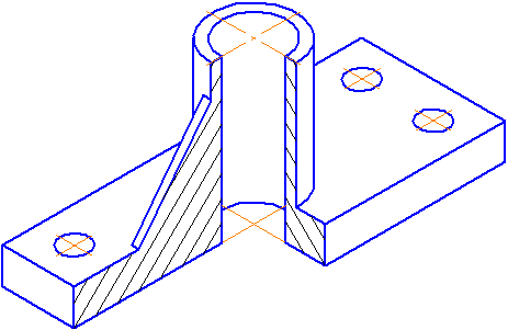
Figure 4.4 – Image of the part in a rectangular isometric projection
4.1.2. Dimetric projection
The position of the axonometric axes is shown in Figure 4.5.
To construct an angle approximately equal to 7º10´, under construction right triangle, the legs of which are one and eight units of length; to construct an angle approximately equal to 41º25´- the legs of the triangle are, respectively, equal to seven and eight units of length.
Distortion coefficients along the OX and OZ axes k=n=0.94 and along the OY axis – m=0.47. When rounding these parameters, it is accepted k=n=1 And m=0.5. In this case, the dimensions of the axes of the ellipses will be: the major axis of the ellipse 1 is equal to 0.95D and ellipses 2 and 3 – 0.35D(D is the diameter of the circle). In Figure 4.5, the major axes of ellipses 1, 2 and 3 are located at an angle 90º to the OY, OZ and OX axes, respectively.
An example of a rectangular dimetric projection of a conditional part with a cutout is shown in Figure 4.6.
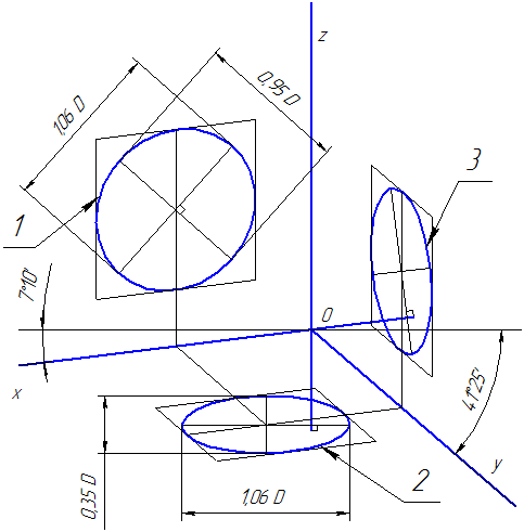
Figure 4.5 – Axonometric axes in a rectangular dimetric projection

Figure 4.6 – Image of the part in a rectangular dimetric projection
4.2 Oblique projections
4.2.1 Frontal dimetric projection
The position of the axonometric axes is shown in Figure 4.7. It is allowed to use frontal dimetric projections with an angle of inclination to the OY axis equal to 30 0 and 60 0.
The distortion coefficient along the OY axis is equal to m=0.5 and along the OX and OZ axes - k=n=1.

Figure 4.7 – Axonometric axes in an oblique frontal dimetric projection
Circles lying in planes parallel to the frontal projection plane are projected onto the XOZ plane without distortion. The major axes of ellipses 2 and 3 are equal 1.07D, and the minor axis is 0.33D(D is the diameter of the circle). The major axis of ellipse 2 makes an angle with the OX axis 7º 14´, and the major axis of the ellipse 3 makes the same angle with the OZ axis.
An example of an axonometric projection of a conventional part with a cutout is shown in Figure 4.8.
As can be seen from the figure, this part is positioned in such a way that its circles are projected onto the XOZ plane without distortion.
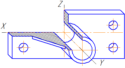
Figure 4.8 – Image of the part in an oblique frontal dimetric projection
4.3 Construction of an ellipse
4.3.1 Constructing an ellipse along two axes
On these ellipse axes AB and CD, two concentric circles are constructed as on diameters (Figure 4.9, a).
One of these circles is divided into several equal (or unequal) parts.
Through the division points and the center of the ellipse, radii are drawn that also divide the second circle. Then through the division points great circle direct parallel lines AB.
The intersection points of the corresponding lines will be the points belonging to the ellipse. In Figure 4.9, a only one desired point 1 is shown.

a B C
Figure 4.9 – Construction of an ellipse along two axes (a), along chords (b)
4.3.2 Constructing an ellipse using chords
The diameter of circle AB is divided into several equal parts; in Figure 4.9, b there are 4 of them. Through points 1-3, chords are drawn parallel to the diameter CD. In any axonometric projection (for example, in oblique dimetric) the same diameters are depicted, taking into account the distortion coefficient. So in Figure 4.9, b A 1 B 1 =AB And C 1 D 1 = 0.5CD. The diameter A 1 B 1 is divided into the same number of equal parts as the diameter AB; through the resulting points 1-3, segments are drawn equal to the corresponding chords multiplied by the distortion coefficient (in our case - 0.5).
4.4 Hatching sections
The hatching lines of sections (sections) in axonometric projections are drawn parallel to one of the diagonals of the squares lying in the corresponding coordinate planes, the sides of which are parallel to the axonometric axes (Figure 4.10: a – hatching in rectangular isometry; b – hatching in oblique frontal dimetry).

a b
Figure 4.10 – Examples of shading in axonometric projections
GOST 2.317-69* (ST SEV 1979-79) establishes rectangular and oblique axonometric projections. Rectangular projections are divided into isometric and dimetric, oblique- frontal isometric, horizontal isometric and frontal dimetric.
Rectangular projections
Rectangular isometric projection. The position of the axonometric axes is shown in the figure at the top left. The distortion coefficient along the x, y, z axes is 0.82; as a rule, it is rounded to 1. Circles lying in planes parallel to the projection planes are projected onto these planes into ellipses (see the same figure just below). The major axes of ellipses 1, 2, 3 are perpendicular to the y, z, x axes, respectively. If the distortion coefficient along the axes is taken equal to 1, then the major axes of the ellipses are equal to 1.22, and the minor axes are 0.71 of the diameter of the circle.
 Rectangular dimetric projection. The position of the axonometric axes is shown in the figure on the right. The distortion coefficient along the y-axis is 0.47, along the x and z axes - 0.94; as a rule, the distortion coefficient along the y-axis is rounded to 0.5, along the x and z axes - to 1. Circles lying in planes parallel to the projection planes are projected onto these planes into ellipses, the major axes of which are perpendicular to the y and z axes, respectively. , X. If the distortion coefficient along the x and y axes is taken equal to 1, then the major axes of the ellipses are equal to 1.06 times the diameter of the circle, the minor axis of ellipse 1 is equal to 0.95, and ellipses 2 and 3 are equal to 0.35 times the diameter of the circle.
Oblique projections
Oblique frontal isometric view. The position of the axonometric axes is shown in the figure below (a). Angle of inclination of the y-axis horizontal line equal to 45°, an angle of 30° or 60° is allowed. The distortion coefficient along the x, y, 2 axes is equal to 1.
Oblique horizontal isometric projection. The position of the axonometric axes is shown in Figure (b). The angle of inclination of the y-axis to the horizontal line is 30°, an angle of 45° and 60° is allowed. The distortion coefficient along the x, y, z axes is equal to 1.

 . The position of the axonometric axes is shown in the figure above (c). The angle of inclination of the y-axis to the horizontal line is 45°, an angle of 30° and 60° is allowed. The distortion coefficient along the y-axis is 0.5, along the x and z axes - 1. Circles lying in planes parallel to the frontal projection plane are projected into circles; in planes parallel to the horizontal and profile planes of projections - into ellipses (Fig. 5.31). The major axis of ellipse 2 makes the x-axis an angle of 7°14", the major axis of the ellipse 3 makes an angle of 7°14" with the z-axis. The major axes of ellipses 2 and 3 are equal to 1.07, the minor axes are 0.33 of the diameter of the circle.
Hatching and dimensioning
The hatch lines of sections in axonometric projections are drawn parallel to one of the diagonals of the squares lying in the corresponding coordinate planes, the sides of which are parallel to the axonometric axes (figure below). Stiffening ribs, flywheel spokes and similar elements falling within the secant plane are hatched.
Examples of images of parts in axonometric projections 
Hatch lines in axonometric projections: a - in rectangular isometric; 6 - in rectangular dimetric; in - in oblique frontal dimetric

Image of a part in a rectangular isometric projection

Image of the part in a rectangular dimetric projection

Image of the part in an oblique frontal dimetric projection

Drawing dimensions in axonometric projections
When applying dimensions, extension lines are drawn parallel to the coordinate axes, dimension lines are drawn parallel to the measured segment (figure above).
Frontal isometric projection is characterized by the fact that all lines of the object parallel to the frontal plane of projections will be depicted in the frontal isometric projection without distortion. The position of the axonometric axes is shown in Fig. 79 . It is allowed to use frontal isometric projections with an angle of inclination of the y-axis to the x-axis of 30 and 60°. The frontal isometric projection is performed without distortion of linear dimensions along all three axes. Circles located in planes parallel to the frontal plane of projections P 2 are projected onto the axonometric plane in a circle of the same diameter. Circles lying in planes parallel to the planes of projections P 1 and P 3 are projected as ellipses.
An object in a frontal isometric projection should be positioned relative to the axes so that complex flat figures, circles, arcs of plane curves were in planes parallel to the frontal plane of projections. Then their construction is simplified, since they are depicted without distortion.
Rice. 79. Image of a circle
in oblique frontal dimetric projection

Rice. 80. Location of the major and minor axes of the ellipse

Rice. 81. Construction of an ellipse

Rice. 82. Oblique frontal isometric
circle projection
Questions for self-control
1. What projections are called axonometric?
2. How is the transition from orthogonal to axonometric coordinates made?
3. What is a triangle of traces?
4. What are the distortion indicators of axonometric axes in rectangular isometric and dimetric projections?
5. What is an axonometric scale?
6. Indicate the distortion coefficients for the major and minor axis of the ellipse - the axonometric projection of a circle belonging to the coordinate plane (or parallel to it) for isometry and dimetry.
7. State Polke’s theorem.
8. What is the difference between rectangular and oblique axonometric projections?
Task: Construct an axonometric projection of a curved line defined in orthogonal projections.

Oblique axonometric projections are characterized by two main features: the plane of axonometric projections is located parallel to one of the faces of the object, which is depicted without distortion; the projection direction is chosen oblique (is equal to the projection plane sharp corner), which makes it possible to project two other faces or sides of the object, but with distortion.
The name frontal or horizontal determines the position of the plane of axonometric projections relative to the main sides or edges of the object.
Axonometric images of objects with oblique projection turn out to be less visual than with rectangular projection. The depicted objects are perceived only as deformed, with a bevel in the direction perpendicular to the plane of projection. However, images in oblique axonometry have an important advantage, which is often used in technical drawing: flat elements of an object, parallel planes axonometric projections are projected without distortion. In drawing, oblique axonometric projections are used in cases where it is necessary to depict parts of an object of a complex curvilinear shape without distortion.
Frontal dimetric projection. The axonometric axes of frontal dimetry are located as follows (Fig. 59a): the OZ axis is vertical, the OX axis is horizontal, the OY axis bisects the ZOX angle and is directed downward to the right. The OY axis can be constructed by setting an angle of 45° from the horizontal. Along the OX and OZ axes, the image dimensions are projected to their true size, and along the OY axis they are halved.
The frontal dimetric projection of a cube with circles inscribed in three visible faces is shown in Fig. 596. In the front face of the parallel XOZ coordinate plane, the circle is depicted without distortion, in the other two faces - by identical ellipses, the major axes of which are equal to 1.07D, and the minor axes are 0.33D, where D is the diameter of the circle inscribed in the faces of the cube. The directions of the major axes of the ellipses deviate from the larger diagonal of the axonometry of the described square (parallelogram) by 7°.
It is advisable to use frontal dimetry in cases where it is necessary to preserve undistorted figures located in the frontal planes, which simplifies the construction of an axonometric image.
Frontal isometric view.
In frontal isometry, the position of the axes (Fig. 60a) is similar to the position of the axes in frontal dimetry. On all axes, dimensions are plotted without abbreviations, in true size. In Fig. 606 a frontal isometry of the cube was constructed. Distortion general form of the depicted object and the unnatural elongation of the cube along the OY axis in this projection is greater than in the frontal dimetry. It is recommended to construct ellipses using eight points. The direction of the ellipse axes coincides with the diagonals of the cube faces.
The location of the axes in frontal isometry, as in other axonometric projections, gives a top view of the object.
Horizontal isometric projection. The axonometric axes of horizontal isometry are arranged as follows (Fig. 61a): the 0Z axis is vertical, the angle between the OX and OY axes is 90°, the OY axis makes an angle of 30° with the horizontal. GOST 2.317-69* allows the use of other angles between the horizontal and the OY axis - 45 and 60°, while the 90° angle between the OX and OY axes is maintained. On all axes, dimensions are plotted without distortion, in true size. The shape distortion and elongation of the cube are directed along the OZ axis. (Fig. 616).
The dimensions of the axes of an ellipse located in a face parallel to the Y0Z coordinate plane are equal to the axes of rectangular isometric ellipses. Instead of this ellipse, you can build an oval. The second ellipse is constructed using eight points. The axes of the ellipse coincide with the direction of the diagonals of the cube faces.
In horizontal isometry, flat figures located on the plan and in horizontal planes are not distorted. This property of projection is used when depicting construction objects in axonometry, when it is necessary to keep the configuration and dimensional relationships of the plan undistorted.
8.2. Orthogonal projections.
Rectangular projection on two and three projection planes.
Axonometric and perspective images have good clarity, but they are difficult to determine true dimensions depicted objects, as well as reproduce them in kind. Therefore, the basis for obtaining images in drawings is the method of rectangular (orthogonal) projection onto two or three mutually perpendicular planes projections. (Fig.62). Rectangular projections (drawings) of an object have the following advantage: if you have the scale and dimensions from the drawings, you can reproduce the depicted objects in exact accordance with the design concept.
Two projections determine the position, shape and dimensions of the object depicted in the drawing; the third projection is determined by the intersection of the corresponding communication lines.
The drawing of the object must give a complete picture of the shape of the depicted object, its structure, dimensions, the material from which the object is made, and also contain information about the methods of its manufacture. At the same time, the drawing of the item must be concise and contain minimal amount images and text sufficient to freely read the drawing, manufacture a part based on it and control it.
For better understanding and reading, drawings should be drawn up according to general rules. All requirements for the design of drawings, as well as symbols contained in the drawings must be uniform. Therefore, when drawing up drawings, it is necessary to be guided by the basic provisions and rules of GOST “Unified System of Design Documentation”. All images in the drawings, depending on their content, are divided into types, sections, sections.
Images of objects in drawings are formed using a rectangular projection of the object onto the projection plane. In this case, it is assumed that the object is located between the observer and the corresponding projection plane.
The object must be positioned relative to the frontal projection plane so that the image on it most fully reflects the shape and size of the object with the best use of the drawing field.
The six faces of the cube are taken as the main projection planes. The object is mentally placed inside this cube (its back face is taken as the frontal plane of projections) and projections of the object are built on each face. If you then expand the faces of the cube until they align with frontal plane, then we obtain images of the object on six projection planes.
On each projection plane, an image is obtained of the visible part of the object facing the observer; such an image is called a view. Depending on the direction of projection, the following names of views obtained on the main projection planes are established: 1 - front view ( main view); 2 - top view; 3 - left view; 4 - right view; 5 - bottom view; 6 - rear view.
The names of views in drawings made in projection connection are not indicated. To reduce the number of views, it is allowed to show invisible parts of the surfaces of objects with dashed lines. The views of an object must be linked to each other, the top view is located below the front view, and the views on the left and right are on the same level with the front view (to the right of it when looking at an object on the left and to the left of it when looking at an object to the right). (Fig.63).
 |
| Rice. 63 |
In order to correctly place images of an object and its parts on the working field of the drawing, you must:
Having chosen the scale of the drawing, determine for each view its main overall dimensions: for the top view - the greatest length and width of the object, for the front view - greatest length and height, etc.;
Convert the resulting dimensions to the selected drawing scale;
Express each image in the form of a rectangle according to the overall dimensions established on a scale;
To determine the format of the drawing, arrange the resulting dimensions in a rectangle with the possible uniform density and taking into account the necessary places for extension and dimension lines and explanatory inscriptions;
After the schematic layout of the drawing, they begin to depict in detail the views of the object inside these rectangles.


