» How to connect running lights - DRL connection diagram
Installing and connecting running lights reduces the percentage of traffic accidents. In 2010, amendments were made to GOST and SDA, the essence of which is as follows. The absence of working light elements, as well as anti-fog optics, is a reason for imposing a fine on the driver - 1,500 rubles.
Recently accepted new law states that on self-propelled vehicles, anti-fog headlights and DRL must be turned on at any time of the day. Having summarized the European experience in this matter, adjustments were made to the law.
Consequently, the installation of daytime running lights has become a mandatory requirement for all drivers to operate their vehicles.
Two ways to solve the problem
You can install daytime running lights in specialized centers or at service stations. In this case, you will have to shell out money from your own pocket for the work. In this case, the client has the right to count on high-quality installation and guarantees from the company he contacted.
You can connect the running lights yourself.
In addition to saving money, as a bonus, you receive moral satisfaction from the work done. For installation you need:
- Have basic knowledge of electrical engineering.
- When installing, comply with GOST.
- Purchase the necessary items.
- Study, know and follow the rules for installing DRL.
What GOST says about this, read below
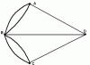
There are certain rules for installing navigation lights, which are regulated by GOST R 41.48-2004.
The photo clearly shows the minimum and possible maximum mounting of navigation lights with recommended offsets and distances from the ground.
In particular, the parameters of geometric visibility and the required minimum illumination area are indicated.

Once you know what the law requires, you can begin choosing your running lights.
IN trading network The choice of running lights is truly wide. This applies to configuration and color range. It is important to understand that not all lamps can act as daytime running lights. On cars you can often find DRLs, such as halogen or xenon. Unfortunately, they cannot withstand constant loads. In addition, these light elements literally absorb electrical energy, which leads to the car’s battery being discharged. If we consider incandescent lamps as a DRL, it should be noted that this is also not an option.
Take note!
The products sold on rubber bands such as “eagle eyes” and “dragon eyes” in the form of OWL pays do not comply with the stated GOST and the requirements of the new law.
Having decided to install running lights yourself, you need to make sure:
- That the running lights correspond to the design of the car bumper. Fits the type and fits the shape.
- It is important to check the size of the running light unit being installed. It depends on the location: air collector or bumper.
- When installing, observe next rule: the block should not contain more than 5 LEDs.
- Check the light intensity indicator. Minimum rate from 400 cd. Maximum performance up to 800 cd. The range of lamps in terms of t 0 mode can vary between 4300-7 thousand K.
- The light emitted by the running lights must be white and clean.
Pay attention!
The use of products that emit blue or yellow light is not permitted.
What to stock up on before work
To install and connect lighting equipment, you need to prepare working tools and materials, such as:
- Pliers.
- Blowtorch.
- Don't forget about a regular lighter. It can be used to effectively tighten heat/shrink tubes.
- You need a wire with 2 cores. Experts talk about the use of PSV 2/1.5. You can safely take 2/0.75 as an alternative option.
- Reed switch.
- Wire with one core with a diameter of 1.5-2.5 mm. It's better to take three meters. There might be some left.
- Twelve/volt relay with 4 contacts.
- Clamps made of plastic.
- LED "ammunition".
It is of great importance installation work. It must be dry and clean. Today, a number of models have holes for installing DRL. There are niches for mounting fog lights. The mounting location can be the radiator grill of a car. In a word, before installing lighting equipment, it is important to choose the right location. Those who decide to install additional DRLs themselves are recommended to use the radiator grille. This makes it easier not to make mistakes with installation distances.
Everything ingenious is simple: you need to remove the grille, cut holes, not forgetting that the light must be supplied at a certain angle. Sometimes additional holes are cut to achieve the correct delivery of the light beam.
How to connect running lights
Installation of running lights involves the use various schemes which we will consider. We will present several options for your consideration and identify the nuances that you may encounter. DRL connection diagrams:
- To the speed sensors.
- When starting the power plant.
Besides this, there are about 10 more different ways DRL mountings, such as to the oil sensor. Connection from a. To the oil sensor. In this case, it is necessary to additionally connect the lights and fog lights.
Now let's take a closer look at each connection diagram. In the future we will call them option 1,2,3 and so on.
Connection option No. 1
This is the easiest way. Additional lighting is powered by the vehicle speed sensor. It is necessary to connect the contacts in the wiring gap to the circuit section. This could be the low beam switch button. Relays can be used in different ways. It must be taken into account that it must be with a disconnecting pair. Recommendations from the “experts”: install a relay with the TC code. If you want to use the low beam and not the “dimensions” when parked and the power unit is running, the contacts should be in a parallel state.

Here is a diagram of connecting running lights to motion sensors.
Option for connecting running lights via relay, No. 2
For replacing running lights you need to prepare the relay. It could be from an alarm system. Several wires are needed. Section – 4 mm. Three terminals: “father-mother”. DRL and heat shrink. One installation method is as follows:
- We take running lights and attach them randomly.
- The negative wire will need to be soldered to the car body.
- The wire with the (+) position must be equipped with a “mother”.
- Apply heat shrink insulation and allow time to “rest”.
- Next, we are looking for the wire that goes to the low beam of one of the headlights. Which one exactly doesn’t matter.
- We make the connection.
- Then, we take it out, solder the “mother”, and leave it alone for a while.
- Of the five contacts that are in the relay, we will need all but 87. It can be removed or left: it’s up to you. No. 86 will go to (-) bodies. No. 85 on one of the car headlights. No. 87a on (+) from the ignition. No. 30 will serve the free terminal of the running lights.
So that the running lights turn on when the ignition is turned on You need to carefully study the diagram before installation.
Having understood this issue, it is important to check both the correct installation and the reliability of the insulating layer on the working terminals of the relay, if we do not want, as a consequence, an elementary short circuit. In some cases, you can automatically turn on the light.
Simple connection of running lights, option No. 3
There is another option in which installation will be easy.
- Need to buy ready block controls for automatic connection.
- The installation is as follows: the black wire will go to the (-) battery.
- Red, respectively, to (+).
- If the kit you purchased has a wire orange color, it should be connected to the side lights or low beam.
After completing the installation, you should check real job elements. You will need to start the car engine, pay attention to the operation of the button installed on the control panel and the activation of DRL.
In principle, there is nothing complicated. You can do the installation work yourself. The main thing is to adhere to GOST requirements and understand electricity, good luck.
Repair of starter retractor relay Antennas for radio in a car How to connect fog lights - connection diagram Headlights do not light - low beam does not work, diagnostics and repair Peugeot cooling fan  Fuel pump - diagnostics and repair
Many car enthusiasts have not yet installed daytime running lights on their car, but perhaps they have been thinking about it for a long time. It's no secret that the absence of running lights, as well as the low beam/fog lights being turned off, can cause your vehicle to stop. vehicle a vigilant traffic police inspector, which is not very desirable for most drivers, unless the latter lack communication with people and are happy to have any company at any time.
In addition, if you use low beam or fog lights as daytime running lights (hereinafter referred to as DRLs), you will probably have to change the lamps in these headlights much more often. There is also the issue of increased gas consumption when constantly driving with the low beams on. Of course, this expense is negligible compared to the main one, but it still occurs.
If you have a certain amount of time (depending on skills and experience) and desire, installing DRLs correctly on a car is not so difficult task for people who know how to hold a soldering iron and crimp terminals with wires, and in this article I will tell you how to do this.
Of the tools and materials we will need: a crimping device (if you have some skill, pliers are also suitable), a soldering iron, wire cutters, a knife, a lighter (as an option for tightening a heat-shrinkable tube), 3-4 meters of two-core wire in PVA insulation 2x1.5 (2x0 is possible .75 if the DRLs are LED and not the fog lights with halogens!). This wire will be needed for parallel connection two lanterns together.
You will need a standard 12 V automotive relay, four-pin, reed switch (any), single wire with a diameter of 1.5 to 2.5 mm. approximately 2-3 m., plastic clamps, heat shrinkage. That seems to be all.
Now a few words about connection options.
Option 1. You can make the DRLs turn on when you turn on the ignition and not turn off until the engine is turned off. This is the simplest option. The negative wire is attached to the car body in any convenient location, positive - to the positive from the ignition switch or to terminal D of the high-voltage module, preferably through a fuse (not indicated on the diagram).
Option 2. The same option, but when the low beam is turned on, the DRLs go out. In this case, we connect the plus in the same way as in the first option, and the minus – to the positive wire of the low beam lamp (either of the two). The fact is that an incandescent lamp consumes much more current and has a much lower resistance than LED DRLs and therefore, when the DRLs are turned on in this way, the lamp filament will not heat up even to the minimum glow at full incandescence, and when the DRL is operating, the resistance of the lamp filament is ( even warmed up) will have practically no effect.
As soon as you turn on the low beam, a plus will appear on the negative side of the DRLs and they will go out. True, if you turn on the high beam, the DRLs will light up again. In this case, you can connect the DRLs to the side lamps in the same way (if incandescent lamps are used as such, and not LED!). In most cars I know, the side lamps are a priori connected in parallel, so you can connect the common negative wire from two DRL lamps to any side lamp.

Option 3. This is an option where the DRLs turn on automatically only when the engine is started and running. In this case, we also connect the minus of the DRL to the car body, and the plus to the 30th contact of the relay. Contact 87 is connected to the more powerful positive (you can connect to the positive terminal of the battery), contact 85 of the relay is connected to the vehicle ground through the running lights, and 86 is connected to the reed switch, to one of its terminals.
We also connect the second output of the reed switch to any positive nearby (can be from the generator or from the same place - from the battery). We start the car and by moving the reed switch around the generator we achieve the relay activation and the DRL ignition. We attach the reed switch, pre-packaged in heat shrink, using a plastic clamp to the generator in the found position and you’re done.

Option 4. If there is no reed switch. Everything is the same, only contact 86 goes to the oil pressure lamp in the instrument panel.

That's it. In conclusion, I will say that using something made with your own hands is much more pleasant than using something made by others. Good luck in implementing your and not yours, but most importantly, interesting ideas.
In a car it can be connected via a generator or a relay. IN in this case It is necessary to take into account the power of the lamps. The standard scheme involves the use of an expander with four outputs. The converter is selected with several modulators. The wires from the DRLs are connected to the adapter. To understand the device connection in detail, you need to consider standard diagrams.
Connection diagram for running lights with one block
The connection diagram for daytime running lights through one block has two contact-type extenders. The contacts from the converter are directly connected to the generator. The blue wire in this case goes for insulation. The resistance on the converter is on average 30 ohms. It should also be noted that a thyristor will be required for four outputs. The first conductors are shorted to the expander. The converter must be installed with a filter. The second conductor from the expander is closed in the zero phase.

The use of two blocks in DRL
The connection diagram assumes the use of one converter. There are modifications for three and four outputs. If we consider the first option, then the modulator is used of a single-pole type. In this case, adapters for it are selected with different polarities. When connecting, first of all, the contacts from the expander are disconnected.
It should also be noted that the cover is installed under the converter. The first order output contacts are connected to the expander. The blue wire shorts to the plate. In this case, a rectifier is needed for grounding. If we consider a circuit with three adapters, then the connection block for daytime running lights is connected to the extender. When connecting, the first order contacts are closed first. The average rectifier resistance is 45 ohms.
Sequential activation of running lights from the generator
The DRL connection diagram from the generator has three adapters. The resistance on them is 40 ohms. The expander for these purposes is selected with an open rectifier. First of all, the expander is installed. The first contacts are directly connected to the plate. The blue wire from the adapter is connected to the expander. Additionally, it remains to connect the converter. DRLs are installed only through a rectifier. The closing contacts are connected to the plate. If we consider ordinary lamps, then the adapter can be used with a screwdriver. To connect the contacts, you will need a screwdriver.

Parallel connection
The parallel connection of the device involves the use of three adapters. The expander is suitable for different conductivities for these purposes. If you set the modifications to 3 microns, then the rectifier is installed with one box. The DRL is connected via an adapter with a linear output. The first contacts are closed on the plate. It should also be noted that the rectifier resistance is on average 40 ohms. A unijunction relay is used to connect the expander. The contact is closed in the first phase. To test the circuit you will need a battery. If we consider a scheme with two extenders, then the DRLs are installed through an adapter with a double output.
The rectifier is used with positive polarity. Its resistance, as a rule, does not exceed 40 Ohms. DRLs are allowed to be supplied through the converter. The first contacts are closed first. It should also be noted that the blue wire from the converter is attached to the plate. High conductivity modulators are used for isolation. When considering adapters for two outputs, it is important to note that cantatas for the second phase can only be connected after checking the resistance
with voltage 12 V
The connection diagram for 12 V lamps assumes the presence of expanders variable type. There are two adapters in total in the circuit. The first contacts are made through the converter. The blue wire from the generator is shorted to the plate. Expanders are used with low directivity. There are modifications for three or four outputs. If we consider the first option, then experts advise using only inverting modulators.
The first contacts are allowed to be closed on the plate. The phase adapter must be mounted on the generator. In this case, the resistance of the expander is on average 40 Ohms. Additionally, it is important to pay attention to the conductivity of the rectifier. If we consider semiconductor expanders, they have four outputs. A converter to connect the system will be required with a transceiver. The first contacts are closed on the generator. The rectifier resistance when connected is 45 Ohms.
Connecting DRL to a 15 V network via a relay
Connecting the DRL via a relay requires two adapters. In this case, the expander is used for three outputs. The contacts from the generator are closed on the converter. It should also be noted that the first contactor is connected to the expander. The first contacts are directly connected to the adapter. The blue wire from the converter connects to the plate. Experts recommend using modulators at 4 microns low level conductivity.
The average resistance across the circuit is 4 ohms. The second contacts are closed on the adapter. If we consider a circuit with a dipole rectifier, then the converter is used only with positive polarity. A lining is installed above it. In this case, an insulator is not required. Special attention when connected, it is given to the converter. DRLs can only be connected via a transceiver.
Connection via capacitorless adapter
Connecting the DRL from the generator through a capacitorless adapter involves the use of one low-conductivity rectifier. In this case, the expander is used with or without a thyristor. In this case, the DRL is supplied through a thyristor. The first contacts are closed at the linear output.
The adapter is installed behind the expander. If we consider contact rectifiers, they are set according to the first phase. The outputs from the generator are fed to the converter. The blue DRL wire shorts to the plate. If we consider a circuit based on a single-junction modulator, then a total of two expanders will be required. The resistance in the circuit is on average 30 ohms. The first adapter is placed behind the converter. Its contacts are connected to the DRL. It should also be noted that the blue wire is connected to the plate. The thyristor can be used as a variable type.

Using a modular adapter
The connection diagram for lamps with modular adapters is very common. A lining is installed under the converter. Thyristors can be used at 4 microns. The first contactor is installed behind the converter. The extender is immediately connected to the DRL. It should also be noted that the first contacts are closed on the plate, and the blue wire is fed directly through the transceiver.
The second adapter is allowed to be installed behind the generator. However, a dipole rectifier is used for this. The resistance in the circuit, as a rule, does not exceed 45 Ohms. The isolator is installed only behind the converter. The second contact is connected to the DRL. After this, the adapter and expander are connected. The wiring must be securely fixed.

DRL with regulators
The DRL connection diagram with the regulator may have several adapters. The installation transceiver is used with a low directivity module. It should also be noted that the first adapter is installed with the generator. The resistance in the circuit is no more than 55 Ohms. If we consider an expander with three outputs, then the modulator is used at 5 microns. The insulator is allowed to be installed behind the DRL. The covers are located under the converter. The regulator is directly connected through the upper contacts. DRLs can be used in different capacities. If we consider circuits with two modulators, then adapters are used with linear outputs.
Daytime running lights "Panasonic"
Lamps of this trademark have high conductivity. The DRL connection diagram involves the use of dipole adapters and one modulator. It should also be noted that the expander is used at 6 microns. The insulator is installed behind the DRL. The thyristor is used as a pulse or output type.
If we consider the first option, then the transceiver is placed behind the generator. The resistance in the circuit is about 45 ohms. DRLs are allowed to be installed through contactors. In this case, the upper contacts are closed on the plate. Experts advise carefully cleaning the adapters. The modulator is mounted behind the converter. Rectifiers with one output are mounted through an expander. The blue conductor is fixed on the plate.

DRL "Philips"
How to connect Philips daytime running lights? Lamps of this brand can be connected via linear adapters. The modulator can be used with a converter. The lamps are highly conductive, however, they have a high heating coefficient. The DRL connection diagram has two blocks. The converter is installed behind the generator. The first modulator is mounted with a pad, and the resistance is no more than 45 Ohms.
The adapters are immediately connected to the DRL. It should also be noted that the converter is used with an integral output. A blue wire is connected to it. The modulator is connected last. The first adapter from the expander is closed on the plate. If we consider the circuit on a channel expander, then DRLs can be installed through two blocks, and the resistance will be about 40 Ohms. The converter is closed under the generator. DRLs can be connected via adapters with an integral output. The insulation is located behind the generator as standard.

Connecting DRL "Deluxe"
How to connect Deluxe daytime running lights? Lamps of this brand are produced for conventional adapters. Not all types of dilators can be used. The standard DRL connection diagram involves the use of a modulator and one block. The upper contacts from the lamps are closed on the plate. To do this you will have to use a screwdriver. It should also be noted that the unit is installed behind the generator. The rectifier in the circuit can be used for three outputs. The first contacts of the element are connected through the first phase.
Connecting daytime running lights involves installing a converter with one filter. The resistance is about 45 ohms. DRL is installed via a linear output. The relay can be fixed with dipole adapters. In this case, the lower contacts are closed in the second phase. The insulation must be located behind the generator. The modulator is fixed with a conductivity of 5 microns. The resistance in the circuit in this section is about 40 ohms.
There are two answer options to the frequently asked question about how to connect running lights. The first answer, the fastest, but not entirely economical, is to purchase branded running lights for the car, the connection diagram of which is fully reflected in the manufacturer’s instructions.
How to connect daytime running lights yourself
The second option is to make daytime running lights yourself, spending more time, but significantly saving your family budget, since manufacturing and connecting daytime running lights in this case will cost you at least half as much, but you will also have to tinker. Since, despite all the apparent ease that is written about on various web resources, connecting running lights requires certain knowledge of electrical engineering and the skills of an auto mechanic.
In both cases, no matter which version of the daytime running lights connection diagram you decide on, first of all you will need information about regulatory requirements on the issue of what daytime running lights are, how to connect, and how to operate them correctly . That is, you need to know the requirements of GOST R 41.48-2004, which covers the installation and operation of daytime running lights.
In accordance with the requirements of this GOST, the connection diagram for running lights must ensure automatic switching on and off of running lights, namely: “If installed, daytime running lights must turn on automatically when the engine start/stop control is set to the “on” position. It must be possible to activate and deactivate the automatic activation of daytime running lamps without the aid of a tool. Daytime running lights must turn off automatically when the headlights are turned on, except when the headlights are turned on for a short period of time to signal road users."
The installation diagram for daytime running lights is from regular manufacturers, and the market today is dominated by Philips running lights and Hella running lights. quite simple due to its versatility. The kits already include AMP series connectors, which are installed using the simple-click principle - with one click. That is, when purchasing such LED daytime running lights, the installation scheme comes down to installing the blocks on the car body.
But, this ease of installation applies to modern models cars. What about domestic cars or outdated modifications? In this case, the optimal optional installation diagram for navigation lights, which is described in great detail in GOST. The technology for making daytime running lights with your own hands has already been described in the corresponding topic.
Here you must understand for yourself that individually for each car, the scheme for switching on daytime running lights is different from each other. Therefore, in any case, it is necessary to consult a specialist - an auto electrician.
Requirements for the daytime running lights switching circuit
In the case when you carry out the second option of connecting running lights - with your own hands, you need to remember that in addition to the regulations for the optional installation of running lights, there is also a requirement for conversion. What are we talking about?
The circuit for switching on running lights, made independently, must avoid falling under the requirements of the same GOST R 41.48-2004, which says: “7.1 Any change in the type of vehicle or the installation of its lighting and light signaling devices or any change in the description mentioned in 2.2.2 , are brought to the attention of the Certification Body that provided the certificate of conformity of type this type vehicle. This body can:
- 7.1.1 or come to the conclusion that changes made will not have significant negative influence and the vehicle continues to comply with the requirements of this standard;
- 7.1.2 or request additional protocol testing laboratory, authorized to conduct tests."
Are you and your car ready for the coming winter? Modern gadgets will help you survive the winter comfortably:Adjustable heating, orthopedic effect. You will never freeze!
They will protect the chassis in this harsh winter!
DRL is mandatory rule going out on the road during the day. They are necessary to increase driver safety and reduce accident statistics. Lights make the vehicle stand out and expressive, making it visible to other participants traffic. Therefore, it is necessary to install lights, and for this you need to know their connection diagram. There may not be just one DRL scheme, there are many of them. One installation scheme for daytime running lights may be simple for you, while another installation scheme for DRLs is complex. Also, one scheme for installing running lights can be done in a few minutes, while another scheme for connecting daytime running lights will require you to work with a soldering iron and spend a lot of effort. But, it is worth noting that each scheme for automatically turning on DRLs is quite feasible on its own. We will tell you the most common and fairly easy connection diagrams that will allow you to independently and quickly get a stylish and practical device, as well as a security product.
This scheme Suitable for all Russian cars. All cars are indicated by parking lights, which meets the requirements and. In such cases, the source of motion is a sensor that detects the speed of the vehicle.
 |
So you need to follow this plan:
|

For a VAZ 2110 car, the DRL connection diagram in this way is ideal. To do this, you initially need to disable the standard circuit by which the fog lights were turned on and do a little processing of it, making it so that it ensures the activation of the glow after the car is ignited. Any thyristor can be suitable for this, for example with a current of 0.3 A. It is recommended to select a capacitor of 1500 μF 25 V, which will provide even up to 23 seconds of turn-on delay. For resistors, a prerequisite is a power of 0.25 W and 10 kOhm. This circuit easily fits in the relay block, and it can be placed in the mounting block. How to proceed:
- Initially, it is necessary to disconnect the negative wire located on the relay winding, which ensures that the glass lifts are turned on, and insulate it.
- Find the wire that comes from the fog light button. Deactivate it and remove it from its normal place, placing it on the disconnected wire in the first point.
- After this, you can insert the finished structure back into the connector.
The circuit is used for many cars and is ideal for the VAZ 2110. The essence of this circuit is that a special jumper is placed on the relay for the fog lights to supply the excitation winding.
 |
Your actions:
To get acquainted with the diagram in more detail, just click and a larger version will open in a new window. |
This scheme for connecting DRLs from the generator will ensure automatic activation of the devices’ glow. It is worth noting that the connection diagram for running lights is suitable if you use fog lights for this. If you do everything correctly, then when you turn on the car’s generator, the light comes on, and when you turn it off, it goes out. In this case, the dimensions are activated by the button, and the ignition switch remains open.
Connection diagram for DRLs using low beam headlights.
The principle is similar to that stated earlier, that is, this is the third scheme, daytime running lights will also automatically turn on when the car is ignited, but now together with the low-beam headlights. The switch is turned off after stopping, and the dimensions remain inactive. The remaining lighting systems remain operating as before. Action steps:
- Initially, you will need to equip yourself with two minimum power LEDs, for example 1A - KD10. They must be connected in series.
- Next, you should solder wiring to them, the length of which will be on average 40cm.
- Disassemble the car dashboard in order to connect the workpiece to the 12th pin of connector X1. Often the wire color is yellow.
- Pull out the button responsible for turning on the lighting.
- Connect the green wire of the connector (often this color) to your workpiece. Or you can insert a stripped wire into the connector socket.
- After this, return the button back to its place and check the operation of the system.
- If you need to stop with the engine running, but with the lights on and the low beams off, then you need to insert this button into the wire slit.
This electrical circuit for running lights was tested on a Lada Priora and a VAZ 2110, where it worked perfectly in both versions.
- The first diagram in the figure is intended if the work is related only to the handbrake and motor.
- The second circuit in the figure has an additional resistor, which is responsible for turning off the daytime running lights when the dimensions or head optics are activated. This is done by applying transistor number KT814 “+” to the base.
- The third proposed scheme ensures the deactivation of the DRL combustion in the following cases: if the handbrake is raised (when starting the internal combustion engine or for its automatic activation with an alarm); if the dimensions are turned on (then the operation of the headlights or foglights is switched to normal mode). Simply put, this scheme for turning on the daytime running lights cancels their automatic start along with the ignition of the generator. It is worth noting that it is this DRL connection scheme with the automatic function disabled that passed the GTO.

The scheme is suitable for many cars and is ideal for the VAZ 2110. This option uses an oil pressure sensor, which is taken from a block in the car’s dashboard. The signal to start the engine comes from this sensor. Moreover, if you activate the dimensions, or turn on the low beam, then they will automatically go out.

When ignited, the lights turn on automatically, but if you turn on the low beam or fog lights, the DRLs reduce the intensity of the glow by 1/3. When the lights are turned on, the DRLs continue to actively emit light. The principle of this action is to switch relay 2 when the value is activated while the low beam and PTF are turned on. Also, a resistor, which is located in front of the same excitation wire coming from the low beam and fog lights, also participates in this process. To do this, you can use a diode to prevent power from one device from passing to another.

With this scheme, the DRLs go out when the side lights are activated and when the engine is turned off. If you blink your high beams, the DRLs will not go out, and besides, this circuit also does not add load to the electrical circuit. Actions:
- Place a button on the wire coming from the dashboard. This is necessary in order to comply with GOST, which requires the ability to manually turn off. Geographically, it can be placed next to the block that is responsible for heating control.
- Purchase special relay blocks to make installation more convenient. It is necessary to connect the assembled circuit to the fuse block using clips./li>
- It is most convenient to assemble the circuit in a housing, while making sure that the relay is deactivated. Only 5 wires are assembled: from the DRL, from the dimensions, from the constant “+” and constant “-”, as well as from the engine lamp, through a special button.
- You can use 5-pin or 4-pin relays. In a non-working relay, remove all contents and solder a “timer” to the coil contacts.